-
Mitalee Parikh authoredMitalee Parikh authored

Output Devices
This week I used an arduino Uno to make a forever spin top spin at different speeds and directions.
I used the Zeotrope tutorial from the Arduino starter kit as it had a similar function.
These are the components I need to control the motor:
- DC motor - only motor I have available now
- H-bridge - IC to control the direction change of the motor
- Potentiometer - to control speed manual input
- Switches - 1 for on/off, 1 for direction change
- Resistors - 10k ohm in series with switches
- Battery 9V - power with connector
- Arduino Uno + Breadboard + Jumper Wires

I refered to this schematic in the Arduino Projects book:
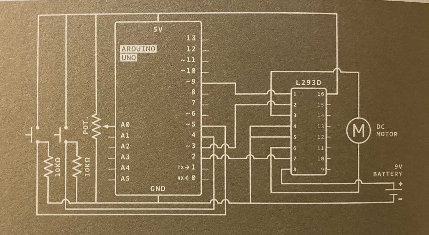
To understand the circuit I arranged everything and marked the functions and connections of each part. And checked the datasheet for H-bridge L298N.
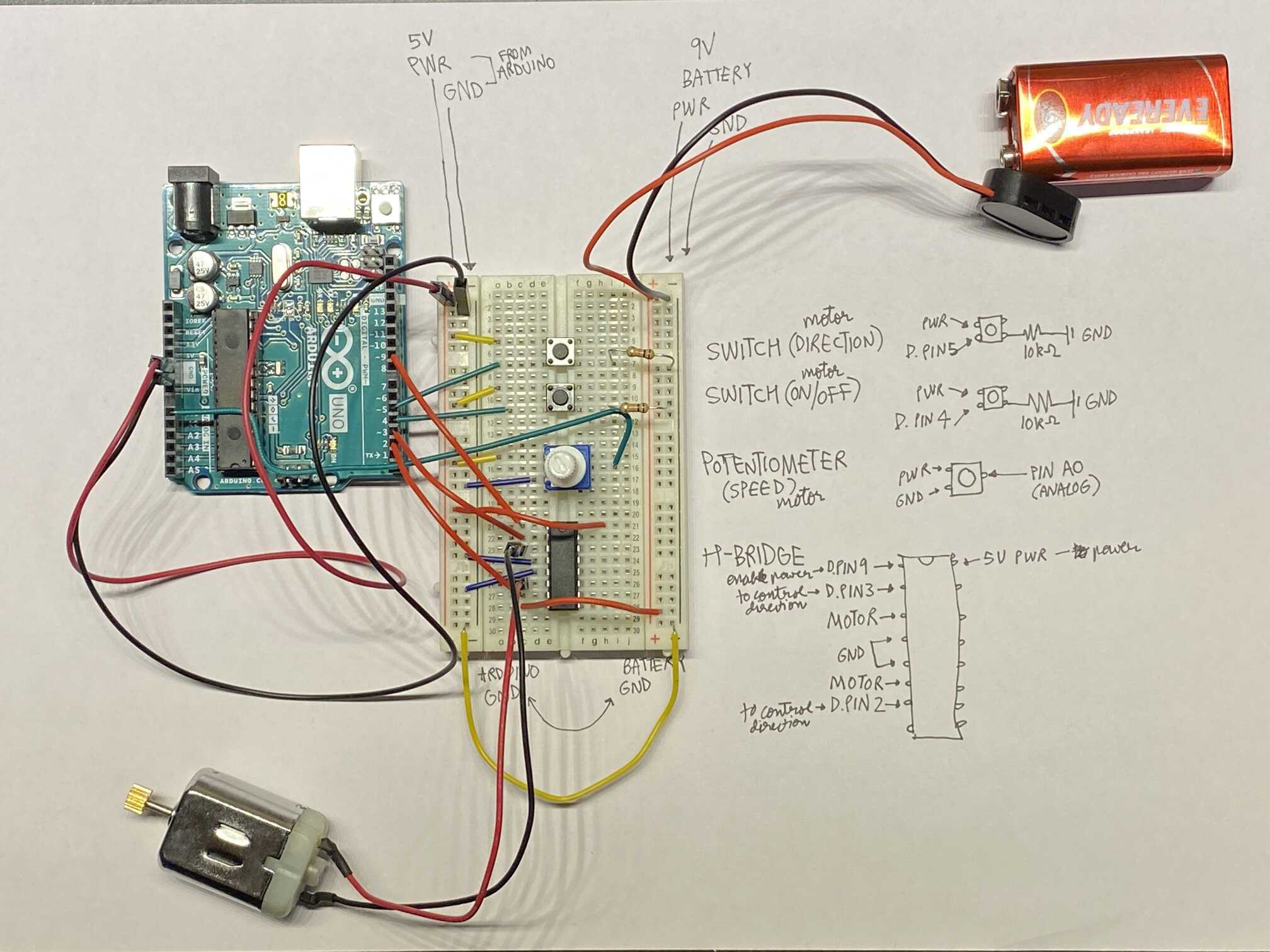
From the above setup, we can see that the pins used are:
Digital Pins :
- 4 for on/off
- 5 for direction change
- 2 for motor control
- 3 for motor control
Analog Pins :
- A0 for speed control
Based on this I defined the constants in the sketch in Arduino IDE.
Then, defined the variables, defined inputs and outputs, setup code, and the loop. Each part is explained briefly in the
sketch.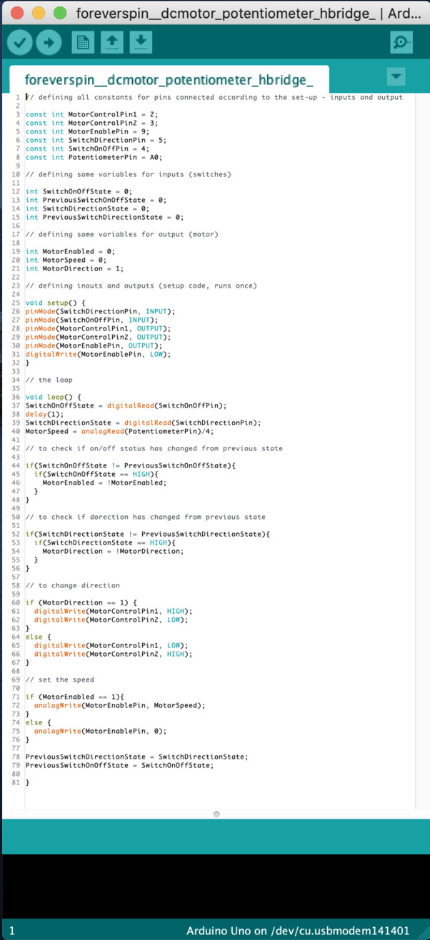
I uploaded the sketch without any errors, but still the motor did not run. I checked all connections and finally had to change my 9 battery.
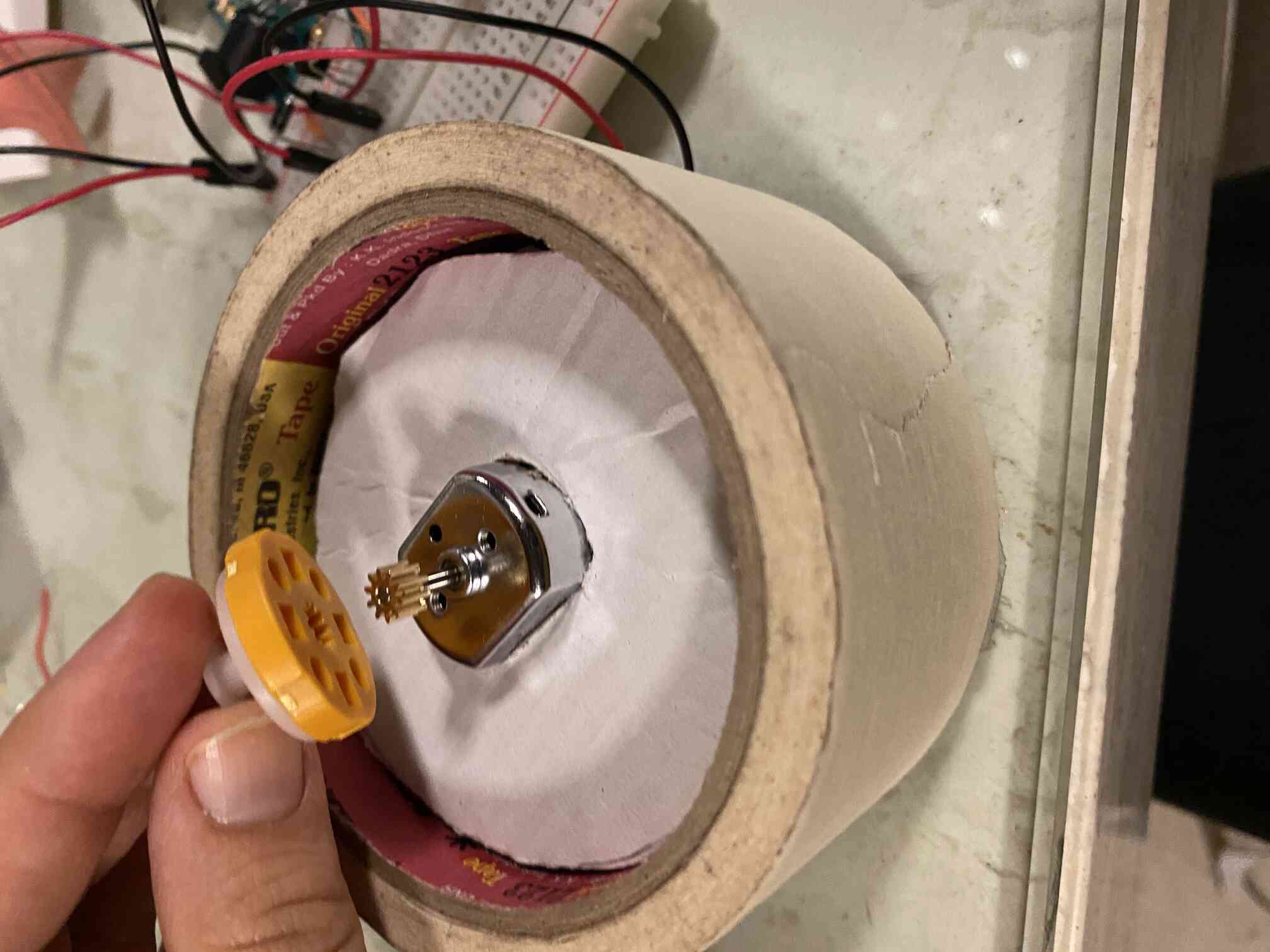
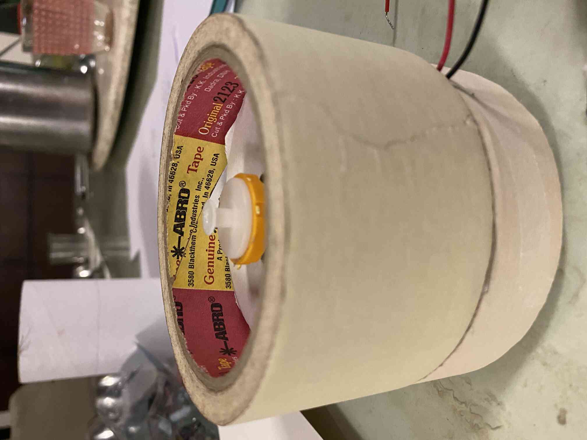
Next, I fabricated a circular base to make the top spin on top from some tape and board I had at home. The pink top was milled by m on a Roland 4-axis milling machine some years back. If in the lab, I would like to make this setup more refined using the machines.
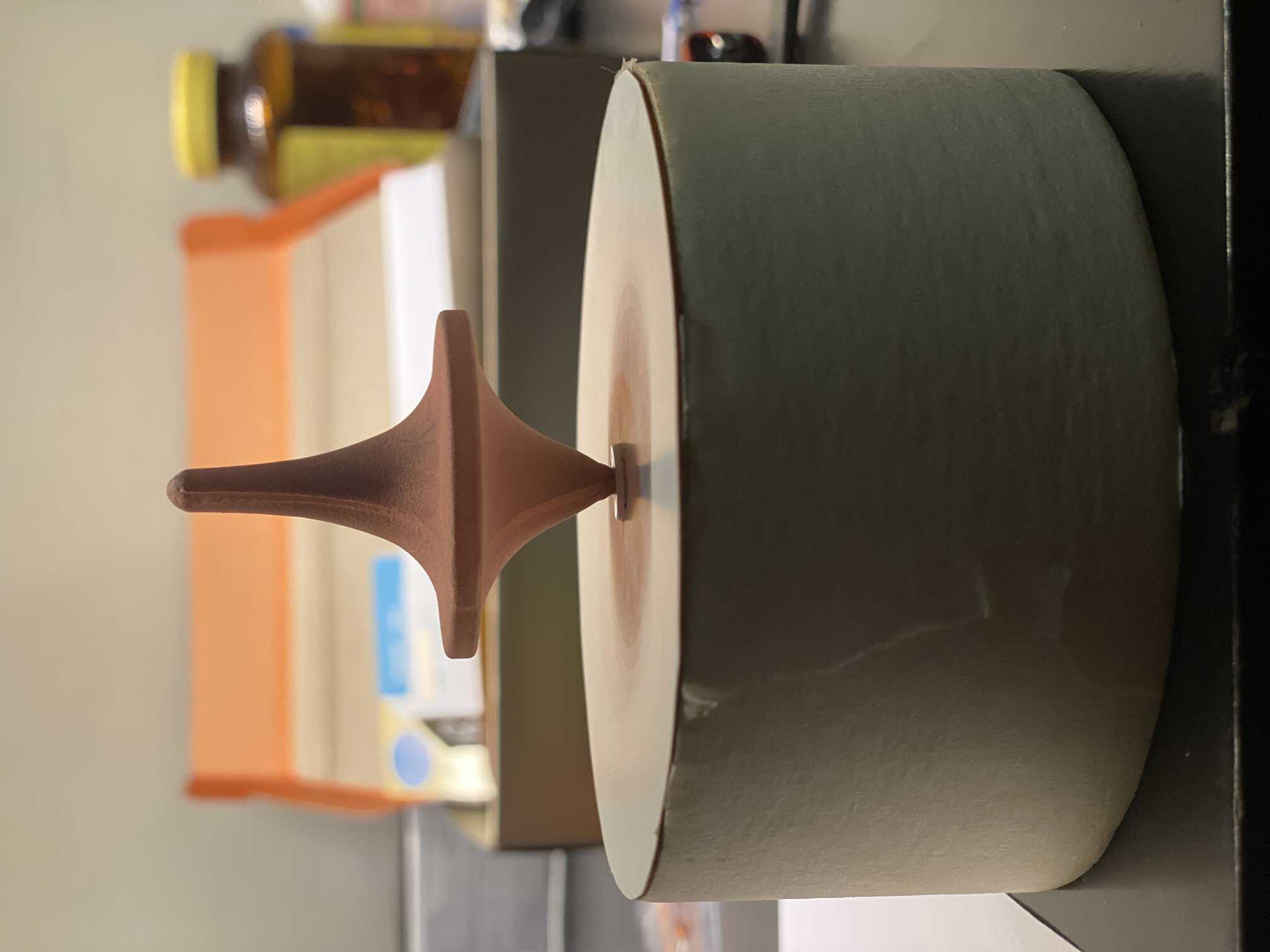
Finally I put everything together and this is the setup for a forever spinning top.
Code
Tutorials
Adding an input sensor
In my arduino kit I had 2 sensors, a temperature sensor and a tilt sensor, I used the latter to make the top spin.
A tilt sensor has a tiny ball inside that connects the legs to complete the circuit, on tilting, the ball loses contact with one leg and breaks the circuit.
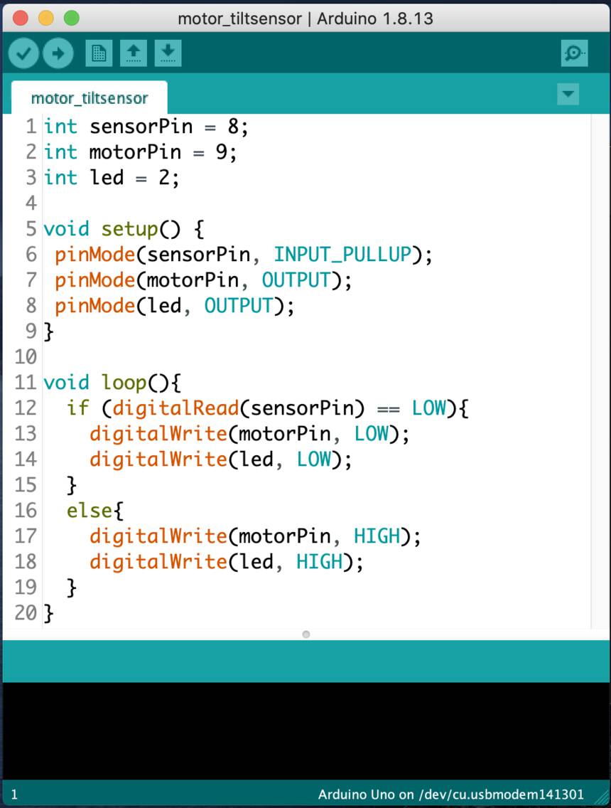
First I made a simple tilt sensor test with led outputs to understand how it works. This was fairly simple. I used this t torial to make leds light on tilting.
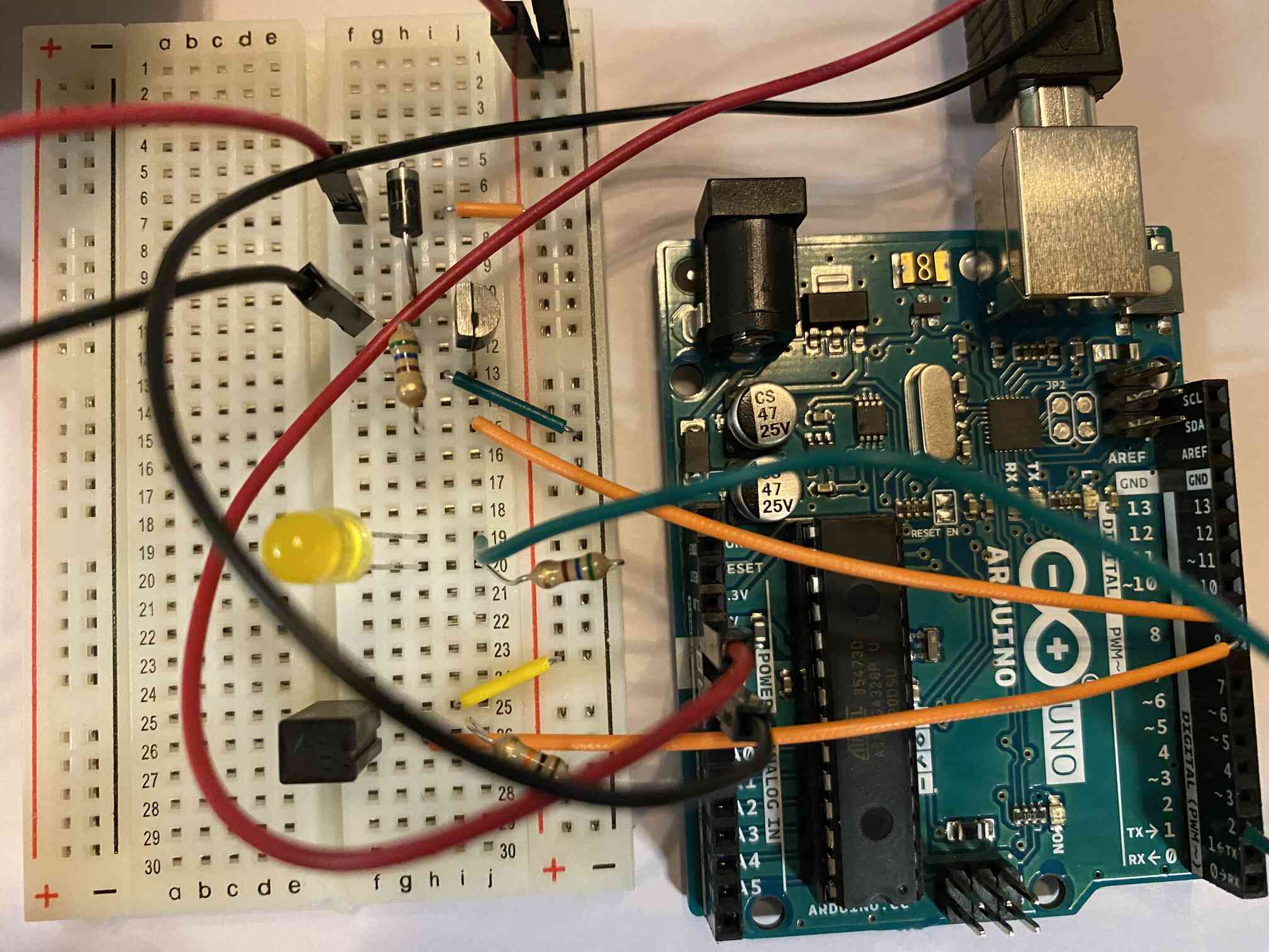
Next, I simplified the DC motor circuit from before by removing the H-brige, the potentiometer and the 2 switches, as I didn't need to change direction or speed.
I referred <a href"https:="" www.tutorialspoint.com="" arduino="" arduino_dc_motor.htm"="">this tutorial for different ways to u e the dc motor. And then did something similar to this.
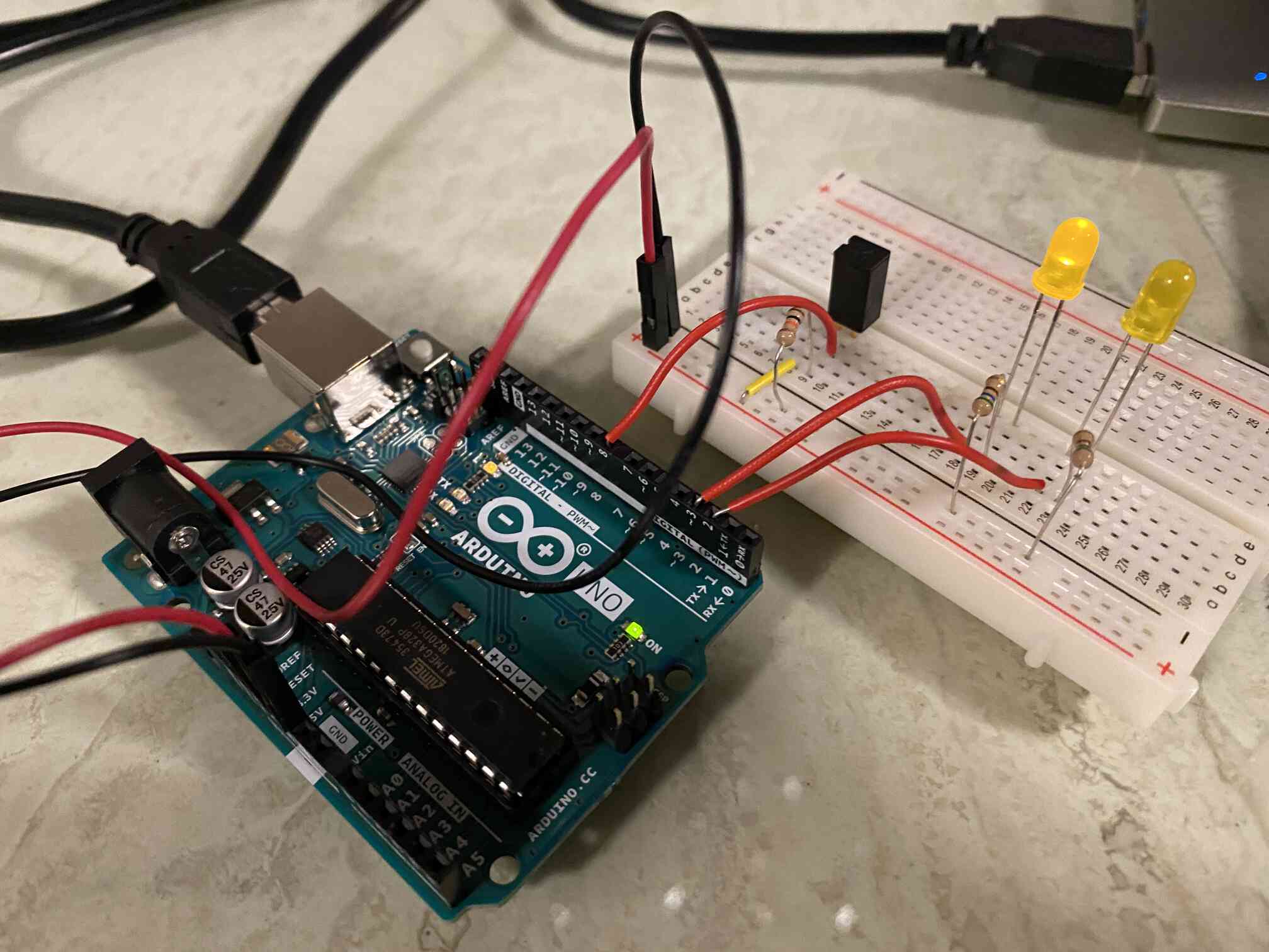
After I got that to work, I combined both sketches to make the tilt sensor the input and the motor the output.
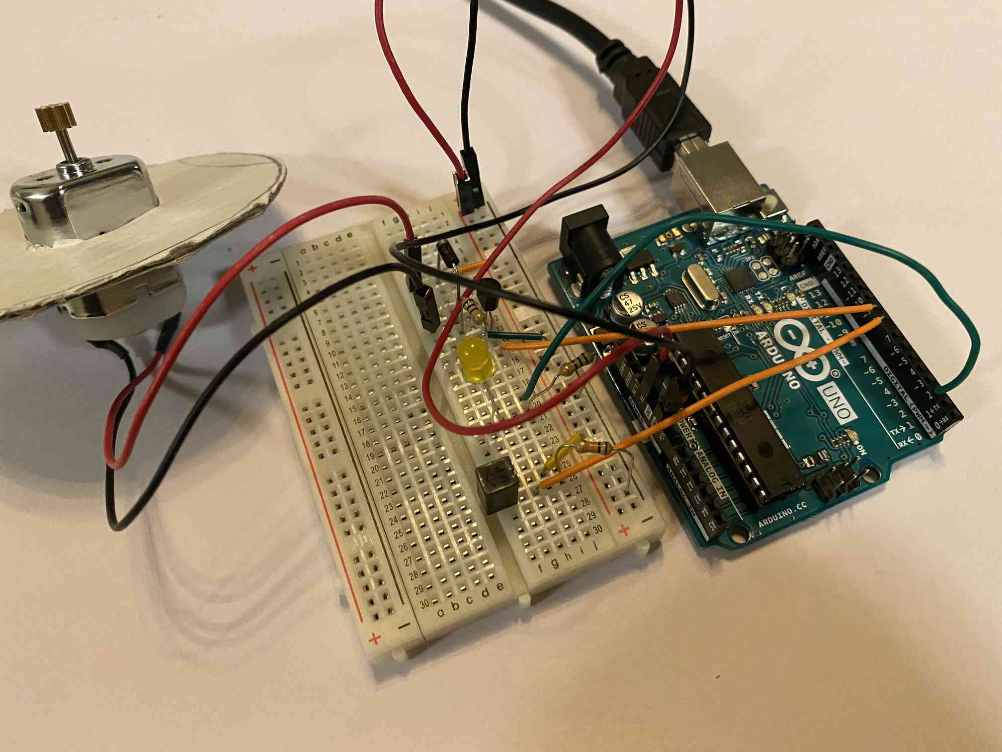
I assembled all components, combining both the circuits
I made some changes to the base, as it was wobbly, and then assembled eveything.
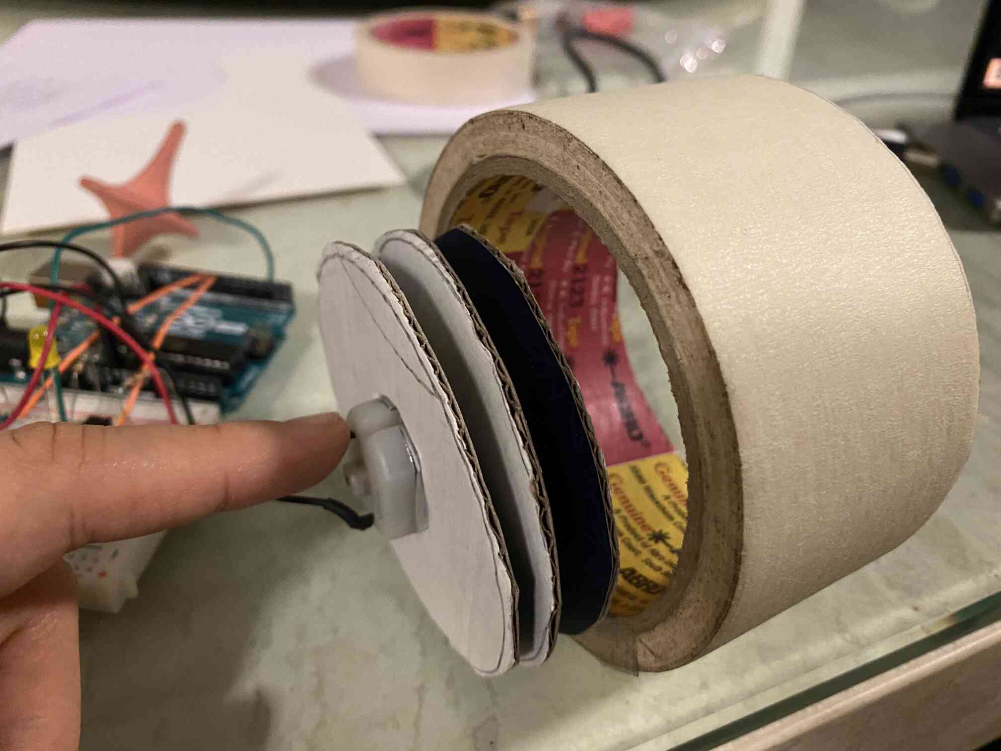
This is the whole setup.
This is a video of it in action
I would like to make the base more refined and add the breadboard and arduino inside, and connect to a battery instead of powering i from the arduino. To make the top spinner.
Code
Only DC motor - sketch
Only tilt sensor - sketch
Tilt sensor + DC motor - sketch