
5. E-Textiles and Wearables I
##Results
#IMAGE IMAGE IMAGE IMAGE
- I made and documented a digital sensor using a bikini clip
- I made and documented an analog sensor using Danish Kroner coins
- I used hard/soft connections with conductive thread and perfboard, pushbuttons and conductive fabric.
- I integrated the bikiniclip switch into a project: a choker that has an alarm system built-in.
#VIDEO VIDEO VIDEO
- Document the sensor project as well as the readings got using the AnalogRead of Arduino
- Upload a small video of the swatches functioning
Basics, research, inspiration
I'm so excited about this week! I have worked with electronics before but have little experience with soft circuitry and e-textiles. So am very happy about the opportunity to learn more this week (by doing!).
During this class I was in Copenhagen so I had to skip this assignment, but I'm catching up now. I had to miss some tutorials, but since I know electronics fundamentals from previous experience and Fabacademy, I mainly studied the (really helpful and clear!) materials provided by Liza Stark on the class page and Kobakant. I've been obsessed with this website for years. It's so good.
Danish Kroner Analog sensor by Plusea
I found these swatches with the Danish Krone slide-switch/softpot by Plusea (Hannah Perner-Wilson) here. Since I was in Denmark this week, I kept a few of my Kroner to try it out!
 Some Danish Kroner I kept from my trip this week.
Bikini clip digital switch
I went through my sewing kit looking for some textile related hardware that might be conductive. I found this nice metal bikini clip, checked it with the multimeter and BOOM! Found my switch.
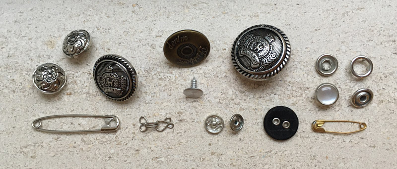 potential switches from my sewing box that didn't make the cut. Loes Bogers, 2019
Other learning yearnings
Atmel ATtiny for programming
I would like to try building and programming the circuit using an Atmel ATtiny85 chip instead of the bulky Arduino UNO. I have all the materials for it and would like to practice being able to solder such a chip onto textile. I've seen the ATtiny chips used in a lot of wearable projects, so even though it's not part of the assignment, I figured it will come in handy to know how to do this later. I have a TinyProgrammer tick i can use: just plug the DIP chip's legs into the programmer. More below.
Home-made and bought lilypad stuff lying around
I previously used some of the open source Lilypad designs by Leah Buechley and recreated them in our lab. It would be nice to reuse some of those, like the TinyLily's I made - using ATtiny chips - with the sewing holes, or the one with the snap-on buttons, or the little LED lights I made with on-board resistors. Oh and I even made some battery clips that I could use now! Let's see. I also have some Lilypad components I bought, like this buzzer. Oooh I want to work with the buzzer as an output.
Tools we want
And I found this page via the Kobakant website where soft circuiteers imagine and share ideas for tools they'd like to have for their practice! Ohhhhh man that is so inspiring! Because I'm not a designer, but I do have maker skills and affinity with these kind of practices I've been thinking about the option of making tools during this course. On this page there are so many ideas! Some of them are built already, others are just sketches.
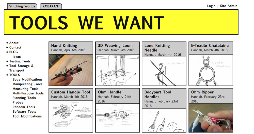 Screenshot of the Tools We Want website, 2019.
I think I might be able to make a better contribution there because I enjoy solving problems, learning about technical stuff and working on concrete things. It gives me more grip on understanding why I'm doing something that makes me feel comfortable. This is my applied streak I suppose. I also love working with artists because they tend to make very weird problems to solve that I'd never come up with but that are very interesting to work on.
##Exploring conductive materials
###Understanding softpot basics
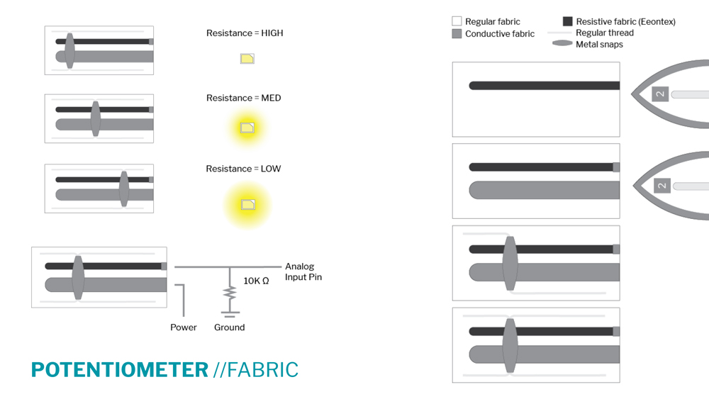
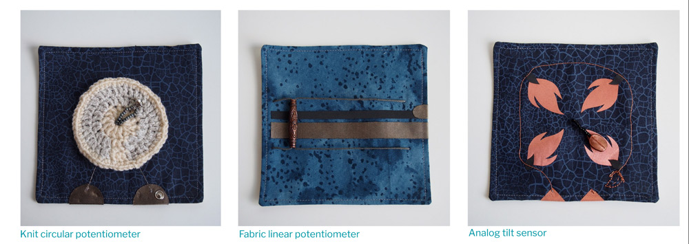 Softpot examples from Liza Stark's slides, 2019
Varying resistance across
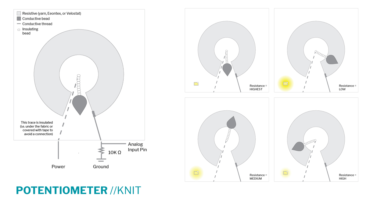
The basic idea of a (soft or hard) potentiometer is to align a very conductive material with one that has resistance, and designing a physical sliding connector that connects them across. The shape or design can be straight or round or even meandering as shown on this swatch from Kobakant:
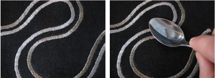 Embroidered potentiometer, screenshot from Kobakant
The sliding connector can be any conductive object or material. The further away you put the sliding connector - or: conductive pointer finger from the source, the more resistance there will be. If you know the the minimum resistance value and the maximum value, you can even map out pretty precise in-between states (as long as your resistive material increases in a linear way, not all materials behave like that).I started out with some conductive and some resistive thread and tried sewing some lines on my sewing machine. It has a lot of patterns preprogrammed and some of them are pretty nice! So I tried a few of those.
Liza Stark's slides made things very simple.
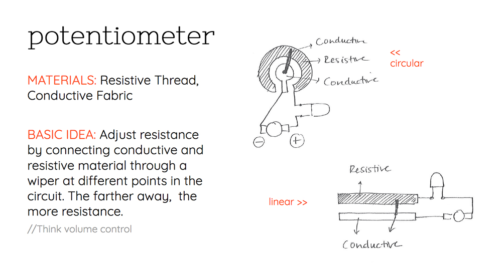 Basic circuit for a softpot, screenshot of Liza Stark's slide, 2019
 Basic circuit for a linear softpot/analog switch, screenshot of Liza Stark's slide, 2019
 Basic circuit for a circular softpot/analog switch, screenshot of Liza Stark's slide, 2019
Tension and test traces
I wanted to sew some test traces with resistive and conductive thread so I could measure how the resistance changed across (and perhaps consider a voltage divider).
The resistive thread was ok to sew as long as I went very slowly (my machine has a limiter for this, called "langzaam naaien" that you can toggle on. Pretty nice. I also had to lower the tension a little. I learned that you can adjust the tension on top with the wheel on the left of my machine, and mine has a front loader spool on the bottom that has a little screw you can loosen or tighten to adjust the tension of the bottom thread.
It wasn't easy to sew in one continuous line without breaking the thread, but I managed at least one lines. Especially when doing patterns it's annoying when it breaks because you break the pattern and will not be able to continue in exactly the right place. Disrupting the continuity of the patter you're trying to make.
The tension between the threads should be equal so each thread keeps to its own side of the fabric :)
Prof. Pincushion on Youtube, explaining tension
Sewing with the conductive thread was a lot harder to do! I didn't quite get the tension right but did sew a zig zag line which for testing purposes was enough. So I connected my multimeter, put it on the Ohm setting and put my Danish krone across to get some readings!
Coated vs. uncoated conductive thread
I thought I was crazy and/or my multimeter was broken because the readings were super erratic. After taking some distance from it (of course this was late in the evening) I realised the conductive thread may have been coated. This means it's still conductive – on the inside - but it's hard to connect to that conductive inside because there's an insulation layer around it.
Cecilia and I tried to melt away a bit of coating from a piece of thread, using a lighter. After removing the coating on two sides I was able to get readings from a piece of thread. It's easy to break this thread while burning it though, it's so thin. I tried melting some off the stitch I'd already done, but this didn't really work. Also, I would need the stitch to be connecting to the slider all across (so I would need to undress the entire length). I drew the conclusion that uncoated conductive thread would probably be better for making this softpot.
Sewing machine dramarama
I found a new thread, barely got one stitch done....and then my machine broke. It has this thing with the pedal that it creates shorts sometimes, driving my machine cray cray. I will have to open it up and dust off the insides and check the connections or connect another pedal (I think I have one somewhere). Ok, well. I see how the basics will work. Moving on to designing the circuit for now.
###Testing a bikini clip/switch
I found this metal bikini clip that I cut off a bikini once. It's really nice! My multimeter says I can use it (beep beep). Great! Off I go to prototype the digital circuit. Emma Pareschi, our electronics miracle worker at the Amsterdam lab provided us with the basic schematics that helped me quickly put together a circuit with a the digital switch and an LED. I'm not sure why she's opted for a pullup resistor here, maybe because the Arduino has an internal pullup so it's easy to switch between. But I'd say it makes more sense to use a pulldown that keeps the buttonState LOW unless pressed. I know you can change it in the code too, so whatever. But basically it would mean putting the resistor on the other end of the button, the one that connects to GND. @Emma can you explain why you use a pullup and not a pulldown? Does it matter?
##Building the digital circuit
###Using Arduino Uno
Prototyping this with an Arduino was a breeze. I started with a Blink sketch, and then added the code from the Button example that come with the standard install of the Arduino IDE under File >> Examples.
tone() and noTone()
Then I proceeded to try get some sounds from the buzzer. I looked up the Lilypad Buzzer hookup guide on Sparkfun and learned about the tone() and noTone(functions). Copied the code, and added my blink and button code to the sketch. I found out later that these functions are not supported on ATtiny however. I has a sad.
LilyPad Buzzer Example, modified by Loes Bogers
SparkFun Electronics

This example code shows how to hook up a LilyPad Buzzer to play a simple song
using the tone() function and setting variables for each note.

Buzzer connections:
   * + pin to 5
   * - to -

const int buttonPin = 8;     // the number of the pushbutton pin
const int ledPin =  10;      // the number of the LED pin > has PWM
const int buzzerPin = 5;    // the number of the buzzer pin
int delayTime = 100;
int delayTime2 = 150;
int delayTime3 = 200;


// Notes and their frequencies
const int C = 1046;
const int D = 1175;
const int E = 1319;
const int F = 1397;
const int G = 1568;
const int A = 1760;
const int B = 1976;
const int C1 = 2093;
const int D1 = 2349;

int buttonState = 0;         // variable for reading the pushbutton status

void setup() {
  // initialize the LED pin as an output:
  pinMode(ledPin, OUTPUT);
  // initialize the pushbutton pin as an input:
  pinMode(buttonPin, INPUT);
  // Set the buzzer pin as an OUTPUT
  pinMode(buzzerPin, OUTPUT);
}

void loop() {
  // read the state of the pushbutton value:
  buttonState = digitalRead(buttonPin);

  // check if the pushbutton is pressed. If it is, the buttonState is HIGH:
  if (buttonState == LOW) {

      //To use LED uncomment sentence below
     digitalWrite(ledPin, LOW);

     //play notes (delayTime in this case is how long it's played)
     tone(buzzerPin, C);
     delay(delayTime);
     tone(buzzerPin, E);
     delay(delayTime2);
//     tone(buzzerPin, C);
//     delay(delayTime);
//     tone(buzzerPin, G);
//     delay(delayTime3);
//     tone(buzzerPin, F);
//     delay(delayTime);
  }else{
//stop sound
     noTone(buzzerPin);
     digitalWrite(ledPin, HIGH);
  }
}
The entire circuit prototyped with an Arduino Uno
###Using an ATtiny85 DIP and Sparkfun TinyProgrammer
About the ATMEL ATtiny85 Microcontroller
There's many Attiny chips, and the 85 sits in a series with comparable chips: the ATtiny 25, 45 and 85. The 85 has the biggest memory (8Kb flash, 512 bytes of RAM, compared to 2Kb/128b for the 25 and 4kb, 256 for the 45). They have the same size
The ATtiny85V has an operating voltage from 1.8-5.5, whereas the ATtiny85 (without V) has an operating voltage from 2.7V - 5.5V which means it will work when you power it with a power supply somewhere within that range. This makes it pretty good for e-textiles that you might want to power with a 3V coin cell, or a 3.7 LiPo battery. It consumes more power as you increase the clock speed, the 85 can run at 20mHz speed but also consumes more.
Any version has a 1Mhz and 8Mhz clock built into the chip, but you can go 16 mHz or up to 20Mhz when using an external clock also called crystal (a small component you would have to add to the circuit to achieve a faster processing speed). You need higher speed for e.g. communication between boards. It supports two protocols that are common to have boards talking to each other: 1-SPI and 1-I2C. You could also make do with the lower ones for simple circuits, it's still pretty fast.
More info and datasheet here. Datasheets are a bit dry but are interesting to find out more about the chip: which pin can do what, if it has any internal pullup resisters you can use etc. For example, the datasheet gives this info on the pinouts and how to use the reset pin. It also details a technical drawing of the device with all measurements, this can be handy if you are designing your own traces that need to fit exactly with the chip.
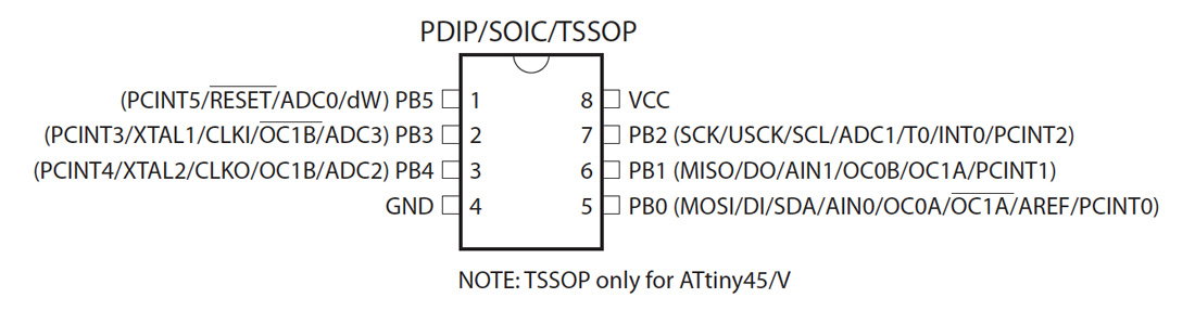 ATtiny 25/45/85 pinouts as listed in the datasheet
It's important to know that these numbers are often NOT the same as the pin numbers you would call in Arduino. For that it's good to look up a tutorial page where they're often listed both alongside one another. Confusing but it is what it is.
 Pinout image from the Sparkfun hookup guide, the Arduino pin numbers are highlighted in turquoise. The red ones indicate which pins you can use for analogReads, the green ones (PWM pins can do pulse width modulation, for e.g. making sounds or fading LEDs.
Tools and instructions
Chips need programmers: Sparkfun's TinyProgrammer stick Sparkfun's TinyProgrammer
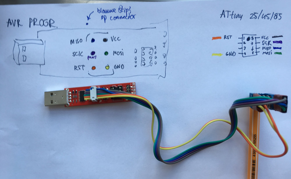
This simple IC is great because it's supported quite well by the Arduino community which means it's easy to program and prototype with. You do need another device to program it though. An Arduino board tends to have a programmer and a chip or IC (integrated circuit) on board, which means you can do the programming with one device. The ATtiny is just an IC so we use a separate programmer. I'm used to working with Sparkfun's TinyProgrammer, and the open-source FabISP. They work the same, just the wiring/connecting is a bit different. I'll document below and also how to connect if you use SMD Attiny chips. Mainly for my own reference for later but who knows it might be useful to others. It's easiest for me with the programmer stick, because you can just plug in the chip and even prototype on the programmer stick. So I'll use that this week.
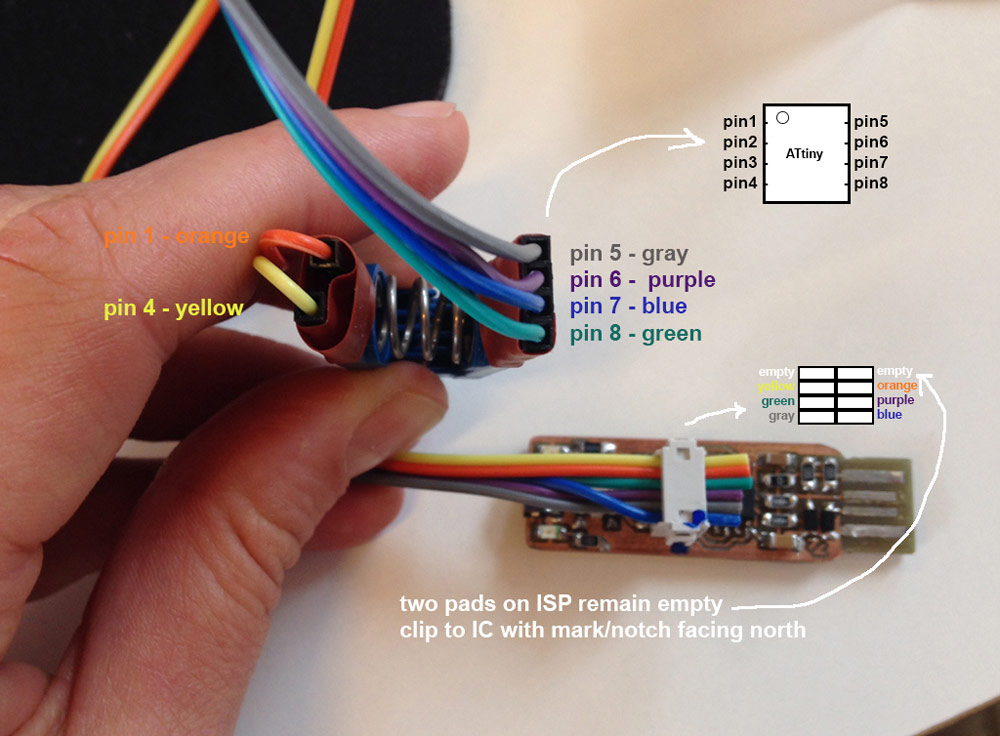
Programming an ATtiny85 SOIC (SMD) with the TinyProgrammer The chip used is a through-hole IC, but they also come in surface mount packages to be soldered onto a PCB. If you want to program those you can do it by using e.g. this Pomona Test Clip with 8 contacts for surface mount attiny's. Wire them us as pictured below:
 How to wire the Pomona testclip to the programming stick, to program surface mount ATtiny chips (SOIC)
FabISP Programmer If you don't have a TinyProgrammer or are against buying hardware you can build, you might already have a FabISP or similar (or want to make one). I documented my learning process of making one here. If you are wiring this guy op to an ATtiny, wire it like this:
 How to wire a FabISP to a testclip to program an SMD ATtiny85
Programming an ATtiny with an Arduino-as-programmer
The book Arduino Wearables:Stitch Your Way To Fashionable Electronics by Tony Olsson details a very comprehensive how to on programming an ATtiny with an Arduino Uno. I would recommend this book for a technical intro, the explanations are very clear. For imaginative and beautifully crafted projects I'd say Kobakant is absolutely leading but they don't explain all their swatches in as much detail. Using an Arduino board as a programmer can be useful because it doesn't require extra hardware to be bought or made! The overview below are a few screenshots from the book.
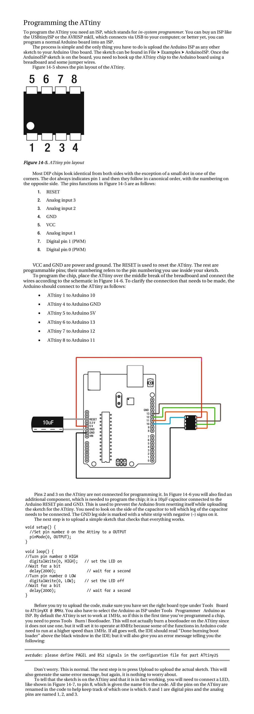 Section from the book Arduino Wearables by Tony Olsson, p. 285-288.
Drivers and installs for ATtiny boards
I bought mine from Sparkfun years ago, they still have it. This tutorial explains well how to set everything up so you can start programming the chip in Arduino.
Choosing settings in the Arduino IDE
Like the tutorial explains, it's important to choose the right board, processor and clock when programming the ATtiny. In my case:
- board: ATtiny
- processor: ATtiny85
- clock: 8 mHz (internal)
The clock is how fast you let the chip run (the frequency or speed at which it cycles through the code). By default, this chip can run on 1 mHz or 8 mHz (it has internal crystals or "clock" devices for that built in). The 1 mHz is too slow so I go for 8, if your blinks are going slower than you set in your code, check if you left the clock on 1 mHz by accident. Don't use the 9, 16 or 20 mHz (external) clocks unless you are also adding a crystal/clock to your circuit with the same value. If you don't know what that means: you're on the safe side sticking to internal clocks, they work fine unless you want to do advanced communication between boards.
Disconnect everything before programming
You might get a lot of errors when trying to program the chip while keeping the rest of the circuitry connected. The pins you use to connect components to are the same pins that are being used to program the chip, so they might interfere with the uploading process.
Connecting and programming the chip (orientation matters)
When moving the chip around always keep track of the orientation! There's a mark on the chip to tell you which side is which. See also Sparkfun tutorial.
Prototyping and breadboarding with the chip (and the programmer)
You can prototype small circuits diretly on the programmer stick, the headers next to the legs of the IC correspond to those pins and are marked conveniently as well. RST, 3, 4 and GND on the left, and VCC, 2, 1, 0 on the right. I needed to use the breadboard too so it was quite a wiry mess but I enjoy that, and it worked out fine.
####Adapting the code to work with ATtiny
no Tone() for ATtiny: stealing some code
I was not getting any sounds from the circuit when I used the ATtiny as IC. I double checked the wiring and code, but it seemed like it should work exactly the same. So I started using the Google and found Technoblogy by David Johnson-Davies who documents lots of experiments and projects using ATtiny chips, including one where he's found a way to use an ATtiny85 with a buzzer. Thank you David!
This code is a bit lower level, programming the chip directly instead of using a library that obscures what is actually happening from the average user's view. I've been able to figure out what is happening in some parts, but will have to ask Emma to help interpreting the note() function he wrote. I was still able to use it though, so moving on....
/*

Code from http://www.technoblogy.com/show?20MO
Playing Notes on the ATtiny85
31st January 2018

Modified by Loes Bogers
November 2019

This article describes a simple function for playing notes on the ATtiny85.
I've called this function note, and it can be used to play notes on the ATtiny85 pins 1 or 4.

The note function uses Timer/Counter1 in the ATtiny85,
leaving Timer/Counter0 free for delay() and millis().
It doesn't use interrupts, so the sound output is unaffected by other interrupt-driven processes,
and it includes a lookup table for the well-tempered scale divisors, so you don't need to remember frequency values.

It's an improved version of my earlier article Simple Tones for ATtiny.
For a similar routine for the ATmega328 or ATmega32u4 see A Lightweight Alternative to tone.

The note function takes two parameters:

    A note number, from 0 to 11, representing the note in the well-tempered scale,
    where 0 represents C, 1 represents C#, and so on up to 11 for B.
    The octave, which can be from 0 to 7 with a 1MHz clock,
    0 to 10 with an 8MHz clock,
    and 0 to 11 with a 16MHz clock.

*/

const int Output = 4;               // Can be pin 1 or 4

// Cater for 16MHz, 8MHz, or 1MHz clock:
const int Clock = ((F_CPU/1000000UL) == 16) ? 4 : ((F_CPU/1000000UL) == 8) ? 3 : 0;
const uint8_t scale[] PROGMEM = {239,226,213,201,190,179,169,160,151,142,134,127};

void setup(){

  }

void loop() {
  for (int n=0; n<=12; n++) {       //n = 12 is number of notes in octave.
    note(n, 4);                    // start at note 4
    if (n!=4 && n!=11) n++;       // if note is not for and not 11 add one to n (plays 8 notes)
    delay(100);                   // delay between each note
  }
  note(0, 0);
  delay(1000);  // time in milliseconds before loop starts again
}

void note (int n, int octave) {
  int prescaler = 8 + Clock - (octave + n/12);
  if (prescaler<1 || prescaler>15 || octave==0) prescaler = 0;
  DDRB = (DDRB & ~(1<<Output)) | (prescaler != 0)<<Output;
  OCR1C = pgm_read_byte(&scale[n % 12]) - 1;
  GTCCR = (Output == 4)<<COM1B0;
  TCCR1 = 1<<CTC1 | (Output == 1)<<COM1A0 | prescaler<<CS10;
}
USB disabled: shorts shorts shorts
My computer kept complaining that the circuit is drawing too much power and the USB port had to be disabled. Oh craps. I had to do some debugging until I found the issues. Also the buzzer stopped buzzing and started behaving very erratically making shreeking sounds.
Potential problem #1:
The Lilypad buzzer is an inductive buzzer...
[...] meaning that is will act as a short to ground if you are not actively driving it. We recommend you put both I/O pins to low (0V) when the buzzer is not used. Lilypad Buzzer specs sheet
So I changed this in the code, by adding a digitalWrite(buzzerPin, LOW);
command. If it wasn't the issue then it's at least good practice.
Potential problem #2:
Faulty wiring. I am shorting my circuit everything I connect the switch ends together because the switch is directly between VCC and GND. The + wire should be connected to VCC not directly, but via the 10K pullup resistor. Errrp my bad. This solved the issues though and I have a working circuit using the components I'd intended. Wahoo! Ready to start crafting it into a textile swatch or project.
The entire circuit with an ATtiny, powered via USB (5V), Loes Bogers, 2019
###Powering the circuit
Now, powering this stuff with a USB cable (5V) is usually fine, but will it blend with say, a 3V coin cell, is what I want to know. The Lilypad Buzzer datasheet says yes, as the operating voltage should be 2.5-4.5V. The ATtiny85 datasheet says 1.8-5.5V for the ATtiny85V and 2.7-5.5V for the ATtiny85. So let's take the latter to be on the safe side. (ATtiny85 Datasheet, and the datasheet of the buzzer used on the Lilypad Buzzer). Ok now that I know this I will try power the buzzer and IC with a 3V coin cell. Went back to simple tone sketch I stole, and...Success!
/*

Code from http://www.technoblogy.com/show?20MO
Playing Notes on the ATtiny85
31st January 2018

Modified by Loes Bogers
November 2019

This article describes a simple function for playing notes on the ATtiny85.
I've called this function note, and it can be used to play notes on the ATtiny85 pins 1 or 4.

The note function uses Timer/Counter1 in the ATtiny85,
leaving Timer/Counter0 free for delay() and millis().
It doesn't use interrupts, so the sound output is unaffected by other interrupt-driven processes, and it includes a lookup table for the well-tempered scale divisors, so you don't need to remember frequency values.

It's an improved version of my earlier article Simple Tones for ATtiny.
For a similar routine for the ATmega328 or ATmega32u4 see A Lightweight Alternative to tone.

The note function takes two parameters:

    A note number, from 0 to 11, representing the note in the well-tempered scale,
    where 0 represents C, 1 represents C#, and so on up to 11 for B.
    The octave, which can be from 0 to 7 with a 1MHz clock,
    0 to 10 with an 8MHz clock,
    and 0 to 11 with a 16MHz clock.

*/

const int ledPin =  0;      // the number of the LED pin > has PWM
const int Output = 4;      // Can be pin 1 or 4

// Cater for 16MHz, 8MHz, or 1MHz clock:
const int Clock = ((F_CPU/1000000UL) == 16) ? 4 : ((F_CPU/1000000UL) == 8) ? 3 : 0;
const uint8_t scale[] PROGMEM = {239,226,213,201,190,179,169,160,151,142,134,127};

void setup(){
    pinMode(ledPin, OUTPUT);
  }

void loop() {
  for (int n=0; n<=12; n++) {       //n = 12 is number of notes in octave.
    note(n, 4);                    // start at note 4
    if (n!=4 && n!=11) n++;       // if note is not 4 and not 11: add one to n (plays 8 notes)
    delay(100);                   // delay between each note
  }
  note(0, 0);

  digitalWrite(ledPin, HIGH);		//visual feedback from LED, to see if program runs
  delay(1000);  						// time in milliseconds before loop starts again
  digitalWrite(ledPin, LOW);
}

void note (int n, int octave) {
  int prescaler = 8 + Clock - (octave + n/12);
  if (prescaler<1 || prescaler>15 || octave==0) prescaler = 0;
  DDRB = (DDRB & ~(1<<Output)) | (prescaler != 0)<<Output;
  OCR1C = pgm_read_byte(&scale[n % 12]) - 1;
  GTCCR = (Output == 4)<<COM1B0;
  TCCR1 = 1<<CTC1 | (Output == 1)<<COM1A0 | prescaler<<CS10;
}
###From schematic to soft circuit
This is the schematic of the circuit I cobbled together. I ended up switching the buzzer from pin 1 to pin 4, which is located on the left side of the IC, because it allowed for an easier layout of the conductive traces. Translating a schematic into a working circuit with a breadboard and jumpers is known territory for me. Making a soft circuit on the other hand: super new! And really quite challenging that I had a lot of fun with and made sooooo many mistakes haha.
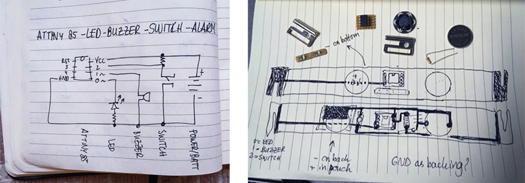 Schematic and first design sketches, Loes Bogers, 2019
###Concept? Who said anything about a concept? As I had to start thinking of the form factor I realized I really didn't have a concept to put these things together at all. I just wanted to work with these components I had lying around. But if you like a story: I made a pink choker that represents the way we use social media. We use it to present ourselves nicely and pretty to the world. It's clear for everyone that it's always passively watching us and capturing us in the background (the red light in the choker), but it's not until we try to take off this leash or try to leave social media that we get alarmed, and continuously nudged into going back into the walled gardens with nosey neighbours. But yeah to be honest: just wanted to explore these particular materials.
###Deciding on a form factor and material I initially thought to put these things into a swatch, but the bikiniclip so strongly demanded a strip as a connection, that I considered a long, stretched out design, that then became a choker.
I only had thin floppy textiles at home – I tend to do electronics development late at night... – and now I see why so many projects, like Jessica Stanley's for example, use (fake) leather or felt. Something relatively stiff and thick yet bouncy is pretty nice to embed electronics in because you don't loose all the form and softness. The rigid and pointy electronics needs some cushioning. So I went back to a leftover of the pink EVA foam I used for the circular fashion week. It was not ideal: you can't make mistakes with stitching, because you can see the holes forever, and it can tear if you're not careful. But it didn't and I'm pretty happy with it as a prototype. I used a standard spool of smooth stainless steel conductive thread that comes on a bobbin. It has a diameter of 0.12 mm and a resistance of 27 Ω/m.
###Sketching up the design
It took several iterations to figure out a way to lay out the traces without crossing them. I wanted to keep it simple and in one layer for now. I was able to do this by moving the buzzer from pin 1 to pin 4. These two are the only pins on the ATtiny that can be used for the buzzer, as described in the Technoblogy article listed above.
The actual prototype (with improv) And then there's reality. I thought I'd planned the design quite well but of course I had taken the hard-soft connections for granted with my previous electronics design experience haha. There are standardized connectors, headers and what not for everything in electronics world. They are so ubiquitous that they become invisible. So I had to do a little improvising along the way. I tried to limit the amount of hardware to embed. I could have used a battery clip but decided to try making a soft connector instead.
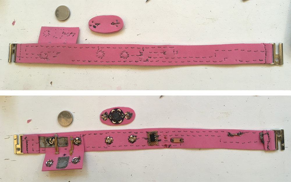 Front and back of the prototype put together. Left to right: clip to GND, battery pouch, detachable buzzer, IC socket and ATtiny, LED board (upside down, facing outward), pullup resistor, clip to sensorPin, Loes Bogers, 2019
DRAWING HERE
Front and back of the prototype put together. Left to right: clip to GND, battery pouch, detachable buzzer, IC socket and ATtiny, LED board (upside down, facing outward), pullup resistor, clip to sensorPin, Loes Bogers, 2019
DRAWING HERE
Final code of the circuit
/*

  Buzzer ATtiny Code from http://www.technoblogy.com/show?20MO
  Playing Notes on the ATtiny85
  31st January 2018

  Modified by Loes Bogers
  Nov 2019

  This article describes a simple function for playing notes on the ATtiny85.
  I've called this function note, and it can be used to play notes on the ATtiny85 pins 1 or 4.

  The note function uses Timer/Counter1 in the ATtiny85,
  leaving Timer/Counter0 free for delay() and millis().
  It doesn't use interrupts, so the sound buzzerPinPinPinPin is unaffected by other interrupt-driven processes,
  and it includes a lookup table for the well-tempered scale divisors, so you don't need to remember frequency values.

  It's an improved version of my earlier article Simple Tones for ATtiny.
  For a similar routine for the ATmega328 or ATmega32u4 see A Lightweight Alternative to tone.

  The note function takes two parameters:

    A note number, from 0 to 11, representing the note in the well-tempered scale,
    where 0 represents C, 1 represents C#, and so on up to 11 for B.
    The octave, which can be from 0 to 7 with a 1MHz clock,
    0 to 10 with an 8MHz clock,
    and 0 to 11 with a 16MHz clock.

*/

const int ledPin =  0;      // the number of the LED pin > has PWM
const int buzzerPin = 4;    // Can be pin 1 or 4
const int buttonPin = 2;     // the number of the pushbutton pin

// Cater for 16MHz, 8MHz, or 1MHz clock:
const int Clock = ((F_CPU / 1000000UL) == 16) ? 4 : ((F_CPU / 1000000UL) == 8) ? 3 : 0;
const uint8_t scale[] PROGMEM = {239, 226, 213, 201, 190, 179, 169, 160, 151, 142, 134, 127};

int buttonState = 0;         // variable for reading the pushbutton status

void setup() {
  // initialize the LED pin as an output:
  pinMode(ledPin, OUTPUT);
  // initialize the pushbutton pin as an input:
  pinMode(buttonPin, INPUT);
  //  // Set the buzzerPinPinPin pin as an OUTPUT   //not necessary, programmed globally?
  pinMode(buzzerPin, OUTPUT);
}

void loop() {

  // read the state of the pushbutton value:
  buttonState = digitalRead(buttonPin);

  // check if the pushbutton is pressed. If it is, the buttonState is LOW:

  if (buttonState == LOW) {

    digitalWrite(ledPin, HIGH);
    digitalWrite(buzzerPin, LOW); // set to low to avoid shorts

  } else {

    digitalWrite(ledPin, LOW);

    for (int n = 0; n <= 12; n++) {   //n = 12 is number of notes in octave.
      note(n, 4);
      if (n != 4 && n != 11) n++;   //
      delay(100);                   // delay between each note
    }
    note(0, 0);
    delay(1000);  // time in milliseconds before loop starts again
  }
}


void note (int n, int octave) {
  int prescaler = 8 + Clock - (octave + n / 12);
  if (prescaler < 1 || prescaler > 15 || octave == 0) prescaler = 0;
  DDRB = (DDRB & ~(1 << buzzerPin)) | (prescaler != 0) << buzzerPin;
  OCR1C = pgm_read_byte(&scale[n % 12]) - 1;
  GTCCR = (buzzerPin == 4) << COM1B0;
  TCCR1 = 1 << CTC1 | (buzzerPin == 1) << COM1A0 | prescaler << CS10;
}
###Hard-soft connections
IC socket made of perfboard
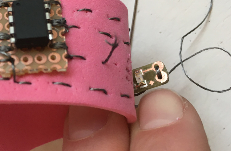
I used a piece of perfboard to make a socket for the IC. It has holes so is easy to sew onto the fabric. I went through the holes 5-6 times, which fills up the hole but still allows you to press the IC in nice and firmly making nice connections whilst being able to remove it easily if you want to reprogram it or replace it (or wash the garment). I saw similar techniques on Kobakant's listings for hard/soft connections.. The foam material is so thick that the legs don't pierce through on the other end, which is extra nice because it's invisible and I can keep the legs intact for programming.
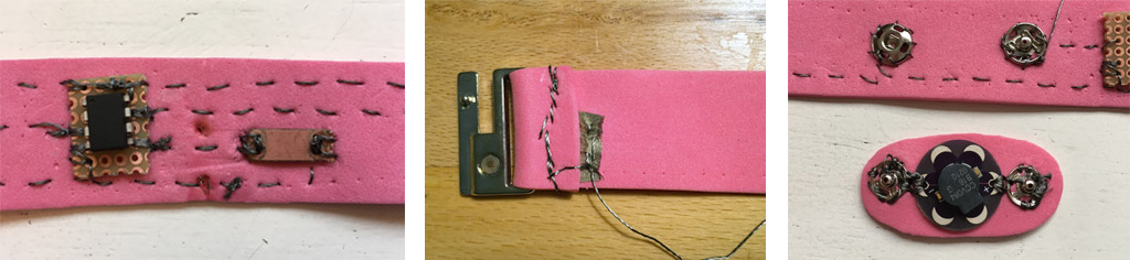 Left: the IC socket and LED pcb, sitting next to a burn mark I'd made replacing the resistor with a jumper, middle: connection with the bikiniclip using a bit of conductive fabric, and right: detachable buzzer pad with push buttons. Loes Bogers, 2019
Bikiniclip connections
I only figured out as I was sewing the bikini clips onto the pink foam that they would not make an electrical connection if I'd just attach them! Haha I needed the thread to somehow touch the clip, which it doesn't do with a standard seam. So I put a small strip of conductive textile inside the fold around the clip before stitching it to attach the clip. Connection sounds good so I'm happy.
Detachable buzzer
I made the buzzer detachable, using push buttons because this module gets damaged if you wash it according to the [Lilypad buzzer specs] (https://www.sparkfun.com/products/8463).
Coin cell battery pocket
I added some conductive textile to make bigger surfaces to connect to the battery's + and GND. And used them in combination with the conductive thread and pushbuttons. They're called bottoni automatici in Italian. Isn't that glorious? Automatic buttons. It reminds me of a time when a push button was seriously new media, and a revelation after all those non-automatic bone and plastic buttons that needed manual handling :D The battery connections could be tighter, but if you wear this on your neck there's a bit of tension that pushes the battery against the pads.
I was getting a lot of shorts because the pushbuttons of the pocket were touching the sides of the battery thereby creating shorts (and very weird beeping sounds from the buzzer). Emma suggested I sew on a bit of rubber band to separate them. Good idea! Not so elegant but a fine prototyping fix.
I should have researched better and I would have found these Twelve Ways To Hold Your Coin Cells at Kobakant!. I will make one of these for the second part of the assignment and do it proper. A bit of additional research also led me to this tutorial "How to Work With Conductive Fabric" which is packed with how-to's and tips on everyting e-textile. I'd like to try making a swatch with traces from conductive textile instead of the stitching technique.
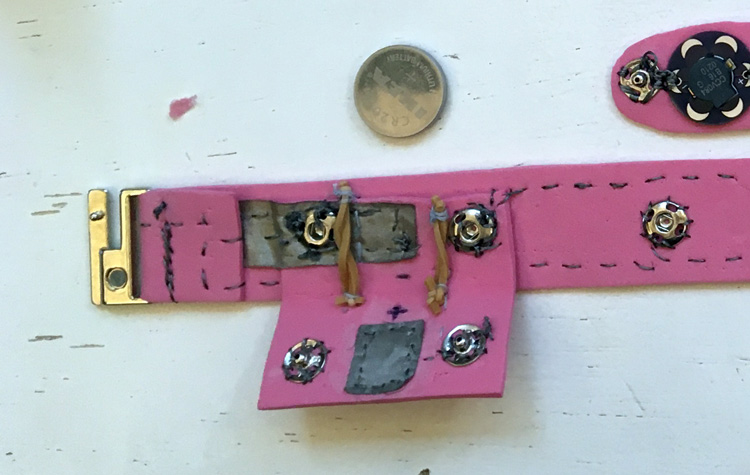 Not the best solution, but an improvised one that works. Loes Bogers, 2019
Resistor and SMD LED on a tiny board
I bent the legs of the resistor to make sewable loops. And I had made some tiny PCB's with an LED taken from the open source files of the LED modules that you can buy as part of the lilypad line. You can find the schematic and design files under "documents", I modified them to match the components I had, milled and soldered them. What I'd forgotten was that I used these for a different purpose at the time 3 years ago. I had to do a lot of debugging before I realized there was a 1K resistor on the LED board. Which is HUUUUUGE for this circuit, and prevented the LED from lighting up. Also, the front and back of these boards are not connected, you have connect them if you want the front and back pads to be connected. Hahahahaha classic mistake. I undid all the stitches, removed the resistor and replaced it with an SMD 0Ω resitor that acts as a wire/bridge/conductor. And presto! Everything works.
 The devil, the details: you know how it is. This is the LED board that was stitched on at the back an not making a connection to the front where the components were. Loes Bogers, 2019
####Front-back-middle?
I spent quite some time thinking about the inside and the outside of the choker, but I would definitely look for more options in a next iteration. I decided to keep the components all on the inside, away from view, and just show the traces to the world. The LED lights up nicely coming from behind the fabric, it gets a bit diffused which I think is very nice. Of course my stitching needs to be way better for this to look nice.
###The art of needlepointing
Ok so I realized that my needlepointing is rather sloppy. I try, but I'm either accidently messing up and putting buttons the wrong way around, or not taking care of my thread allowing it to know, or I'm basically just impatient. I do see that it's a huge part of the aesthetic you can achieve though and would like to improve this and learn some different stitches.
Next time I'll only hand stitch sitting down with a glass of wine and a nice friend or music, and try to really enjoyyyyy doing this repetitive but important job carefully and nicely. It's a kind of finesse that I would really hope to one day bring to my electronics projects.
For now: look at these stitches, they are not that bad! Don't look at the other ones please. I used a little rotary pointy tool to draw even dotted lines that helped with stitching in a regular rhythm. But still: Ceciia could you bring us your needlepointing bible?
 Left: me trying to sew on some pushbuttons neatly (tongue pressed between my lips and all), middle: me finding out that I sewed it on upside down....right: maybe this tool will save my traces? Loes Bogers, 2019.
###Debugging tips and tricks
Yeaaaasssss my favourite part haha. I get to practice my mindfulness and sense of humour here because this never goes as expected. I used to get so frustrated! Now I understand a little better that it's just part of the process and it's actually a nice puzzle somtimes. I was very hopeful it would work right away. Which is partially did. I was getting a buzzer, and it would stop as the clip connects. But I got a lot of shorts with the battery pocket, like I described (I heard weird sounds at times and saw that the LED was not turning on when expected. It took half a day to figure out why the LED wasn't coming on. It was because the top and bottom of the board were disconnected and I was connecting the back whereas the front has the components on them. Hot tip: do not seal your connections with hotglue until everything works, it's impossible to probe your circuit with nailpolish or hotglue everywhere....
If something is not working or behaving weirdly, I use these debugging strategies I learned from Emma during Fabacademy:
Debug the connections
- Measure each connection all the way across (using continuity mode), ALSO check that the other traces or not accidently also connected to the trace you're trying to check. Check two things: 1) check whether traces/pads that should be connected are connected, and 2) check whether traces/pads that should be separate are indeed not connecting anywhere. You cannot check this enough in my experience.
Debug resistance, current and voltage
- Measure voltage of the battery to see if it's full enough
- Read datasheets and check the operating voltage (your power source should accommodate the operating voltage of all the components used).
- Measure voltage across the chip (should be same as voltage of battery)
- Measure voltage on pins on the IC that should be high according to your code (should give same voltage as the battery).
- Feel the components: is stuff getting hot? Do you smell something burning? Your circuit is drawing too much power and you probably have a short. Disconnect the power immediately and debug. Check whether you've burned any components one by one.
- If you are powering your project with a laptop, it will disable the USB ports if it's drawing too many Amperes (to protect your computer from frying). This should tell you you need to look for shorts.
Check the code:
- If all seems right, also check the code. Did you connect the right components to the right pins mentioned in the code?
- Did you make sure your code is not stuck in a loop? Sometimes I write something and I don't realize it can never reach certain states or conditions. For each control statement, write in a feedback loop so you know where in the code you get stuck. E.g. make a led blink once or twice or three times, as it loops through the parts of the code. Or use the serial monitor and print messages to the serial to know what the code is doing and where it might get stuck.
For example: I might try to connect a buzzer but am not sure how to connect it. In my code I'll write a command to play a note on the buzzer, and also turn on an LED. If the buzzer doesn't play a tone but the LED turns on I know that the program is running correctly and I probably have to look at the way I connect the component or how I drive it in the code. If there's no tone AND no light, it probably means the program never reaches that part of the code.
Ugh, despair. Why didn't I record the results right away? I didn't document the working piece straight away when it was working. And when I tried to do it this evening. It was buggy again. More debugging for me :(
I found that it was the connection to the power supply (the coin cell battery) was the issue. When I power the choker with the lab power supply it works perfectly (see video).
So I took off my improvised battery pouch, and replaced it with a hard battery clip to fix the problem.
And it's workinggggg also with only the coin cell, Loes Bogers, 2019
##Analog sensor: black diamond capacitive sensing rock
I grew some alum crystals in week 9 - Textile as Scaffold. I missed this electronics week so I'm working on week 5 from the future. I made these beautiful crystals with the addition of some bare conductive ink. The documentation is here
And I made this baby work! I wrote some code for Attiny85 using softserial to see how it's reading and it's beautiful. I had the sending and receiving pin the wrong way around at first but that was easily fixed.
//Code taken from these tutorials and modified by Loes Bogers
//https://www.instructables.com/id/Capacitive-Sensing-for-Dummies/
//https://www.arduino.cc/en/Tutorial/Smoothing

#include <CapacitiveSensor.h>

#include <SoftwareSerial.h>   when using ATtiny and FTDI cable

#define rxPin 1   //    if using FTDI cable and attiny > connect to TX of other device
#define txPin 0   //  if using FTDI cable and attiny  > connect to RX of other device
SoftwareSerial serial(rxPin, txPin);  //if using FTDI cable and attiny

//send at pin 4, receive at pin 3, 1-10M ohm resistor between
CapacitiveSensor cs_3_4 = CapacitiveSensor(3, 4); // 1-10 megohm resistor between pins 4 & 3, pin 3 is sensor pin, add wire, foil

const int numReadings = 10;     // size of array/number of readings to keep track of (higher = slower)
int readings[numReadings];      // the readings from the analog input
int readIndex = 0;              // the index of the current reading
int total = 0;                  // the running total
int average = 0;                // the average

void setup() {

  // initialize serial communication with computer:
//  Serial.begin(9600);           //start serial communication via USB cable
  serial.begin(115200);       //if using FTDI cable and attiny

  cs_3_4.set_CS_AutocaL_Millis(0xFFFFFFFF); // turn off autocalibrate on channel 1 - just as an example Serial.begin(9600);

  //initatialize readings array setting all values to 0
  for (int thisReading = 0; thisReading < numReadings; thisReading++) {
    readings[thisReading] = 0;
  }
}

void loop() {

  // subtract the last reading:
  total = total - readings[readIndex];

  // read from the sensor:
  readings[readIndex] = cs_3_4.capacitiveSensor(30);

  // add the reading to the total:
  total = total + readings[readIndex];

  // advance to the next position in the array:
  readIndex = readIndex + 1;

  // if we're at the end of the array...wrap around to the beginning
  if (readIndex >= numReadings) {
    readIndex = 0;
  }

  // calculate the average:
  average = total / numReadings;

  // send it to the computer as ASCII digits
//  Serial.println(average);  // if using Arduino serial
  serial.println(average);       // if using FTDI cable and attiny

  delay(10); // arbitrary delay to limit data to serial port
}
Basic code for capacitive sensing with a black diamond, Loes Bogers, 2019
I translated this circuit into a swatch
INSERT SWATCH
##Building an analog needle felt squeeze sensor
I had this conductive wool so started off making a sensor with that. I saw it here first :)
The schematic
Multimeter reading Unstable reading of the dot but somewhere beteen 200-300ohm without squeezing, to totally conductive (beeeeeeep!) when I squeeze it. The kobakant tutorial suggest to mix in some normal wool to make it more resistive but I don't have that lying around so will just make do here for now but I can see how this would give me a rather limited range. So let's see how far we can stretch it.
Code: analogRead to serial This difference in resistance reads on between 1000 and 1023 on the analogRead pushed to serial. It only occasionally drops below. So thats a pretty small spectrum.
Code: constrain() and map() I map the 24 step range to a range of 0-255 (the range I can drive a LED with later, using pulse width modulation.
Code: analogRead to plotter Can be handy because more visual. Use right syntax though.
Code: AnalogWrite or Pulse Width Modulation to fade LED Sends it as a wave that we perceive as continous.
Code: smooth()
What does this do?
Array
Average
I used a delay of 100 milliseconds to be able to read the readings from the serial monitor more easily, but it made the LED fading jittery and it would fade away very slowly. Turning down the delay at the end to 50 milliseconds made it more responsive.
###Wool dot swatch
Hard/soft connections
The dot One connection to GND via pulldown resistor, one connection to AnalogRead pin on side, and on the other side connected to VCC. So three connection point to connect this sensor swatch.
LED I'm adding the LED because it's nice to be able to get feedback. And it's a very nice LED! One leg to a PWM pin, one to GND
Sketching a design
##Building another analog circuit
Here are my Kroner! Sitting on a paper circuit sketch. I collected some very nice leather samples from the lab for making swatches now that I know my rolling pin is a leather wheel :) The basic swatch consists of a a conductive trace to VCC, a resistive trace going to a pin that can do an analogRead, and connected to GND via a pulldown resistor. The Kroner is the wiper hand that connects the two traces at a position you can adjust by sliding it along the traces.
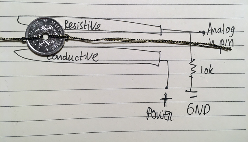 Does this count as a schematic? ;) Loes Bogers, 2019
###Using Arduino Uno
CODE CODE CODE
###Using an ATtiny85 DIP
###Planning the connections: Analog sensor
Schematic
Design
Hard-soft connections