-
omaralaqtash authoredomaralaqtash authored

Final Project
Mr. Fransisco has asked us to think about final project using one input and one output. Also, he told us that we have to use more than two machines from the fablab machines to produce the prototype of the final project.
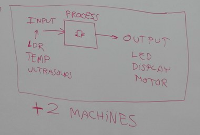
I have decided to build an automatic light system by using the Attiny 44 microcontroller IC, PIR sensor (motion detector) as an input and light as an output.
The idea of this project is to automatically light the way for the guests who will come to visit you; once the PIR sensor detect any body, the light will turn on, otherwise the light will stay in the off state.
Moreover, the circuit of the final project will be powered by solar energy system and rechargeable batteries.
First Iteration
First of all Mr. Fransisco asked us to make a prototype of the project by using pieces of cartoon to have an idea about the final shape of the prototype in order to have all the details before start doing it by the machines. Also, we have to sketch the circuit diagram of the electronic circuit and calculating the values of the components that we will use.

PCB Design
I have started designing my circuit board using the kokopelli software. After I had finished designing the circuit board, Mr. Fransisco recommended me to reduce the size of the circuit board because there were many empty parts within the designed circuit board, and he told me that the small circuit boards are more attractive for people.
In order to design the circuit board I have copied the code text where all the components are defined from this link. Then I started writing my own code text for designing in define board section. The text for my circuit design was as follow:
# define board
#

w = .016
width = 1.29
height = 0.93
mask = .004
x = 1
y = 1
z = -.005
d = .06

pcb = PCB(x,y,width,height,mask)

IC1 = ATtiny44_SOICN('IC1\nt44')
pcb = IC1.add(pcb,x+.23+0.4,y+.59,z)

J1 = header_ISP('J1\nISP')
pcb = J1.add(pcb,IC1.x+.05,IC1.pad[7].y-.22,z,angle=90)

pcb = wire(pcb,w,IC1.pad[8],J1.pad[1])

pcb = wire(pcb,w,IC1.pad[9],J1.pad[3])

pcb = wire(pcb,w,IC1.pad[7],point(IC1.pad[7].x+.01,J1.y-.02,z),J1.pad[4])

pcb = wire(pcb,w,IC1.pad[4],J1.pad[5])

pcb = wire(pcb,w,IC1.pad[14],point(J1.x-.05,J1.y+.02,z),point(J1.x+.05,J1.pad[2].y-.08,z),J1.pad[6])

J2 = header_FTDI('J2 FTDI')
pcb = J2.add(pcb,x+width-.22,IC1.y-.0,z,angle=0)

pcb = wire(pcb,w,J1.pad[2],point(J2.x+.08,J2.pad[3].y,z),J2.pad[3])

pcb = wire(pcb,w,IC1.pad[13],point(IC1.pad[13].x+.24,J2.pad[4].y,z),J2.pad[4])

pcb = wire(pcb,w,IC1.pad[12],point(IC1.pad[12].x+.2,J2.pad[5].y,z),J2.pad[5])

R1 = R_1206('R1\n10k');
pcb = R1.add(pcb,IC1.pad[1].x,IC1.pad[1].y+.1,z)

pcb = wire(pcb,w,R1.pad[1],IC1.pad[1])

pcb = wire(pcb,w,J2.pad[3],point(J2.pad[3].x+.08,R1.y+.06,z),R1.pad[1])

pcb = wire(pcb,w,R1.pad[2],J1.pad[5])

C1 = C_1206('C1\n1uF');
pcb = C1.add(pcb,IC1.pad[14].x,R1.y,z)

pcb = wire(pcb,w,IC1.pad[14],C1.pad[2])

pcb = wire(pcb,w,C1.pad[1],point(C1.pad[1].x,C1.y+.06,z))

pcb = wire(pcb,w,J2.pad[1],C1.pad[2])

REG = regulator_SOT223('REG');
pcb = REG.add(pcb,IC1.x-0.28,1.46,z)

C2 = C_1206('C2\n10uF');
pcb = C2.add(pcb,REG.x-0.09,REG.y-0.28,z,90)

C3 = C_1206('C3\n10uF');
pcb = C3.add(pcb,REG.x+0.09,REG.y-0.28,z,90)

solar = D_1206('D');
pcb = solar.add(pcb,REG.x-0.25,REG.y-0.22,z)

solar2 = C_1206('+');
pcb = solar2.add(pcb,REG.x-0.25,REG.y-0.1,z)

pcb = wire(pcb,0.068,solar2.pad[1],solar2.pad[2])

pcb = wire(pcb,w,solar2.pad[1],solar.pad[1])

solar1 = C_1206('-');
pcb = solar1.add(pcb,REG.x-0.25,REG.y-0.345,z)

pcb = wire(pcb,0.068,solar1.pad[1],solar1.pad[2])

pcb = wire(pcb,w,solar1.pad[1],C2.pad[1])

pcb = wire(pcb,w,solar.pad[2],C2.pad[2])

pcb = wire(pcb,w,C2.pad[2],REG.pad[1])

pcb = wire(pcb,w,J1.pad[6],C3.pad[1])

pcb = wire(pcb,w,J1.pad[6],C2.pad[1])

pcb = wire(pcb,w,J1.pad[6],REG.pad[2])

pcb = wire(pcb,w,REG.pad[3],C3.pad[2])

S = C_1206('I/N-S');
pcb = S.add(pcb,REG.x+0.,REG.y+0.29,z,90)

pcb = wire(pcb,0.068,S.pad[1],S.pad[2])

pcb = wire(pcb,w,IC1.pad[2],S.pad[1])

G = C_1206('GND');
pcb = G.add(pcb,REG.x-.15,REG.y+0.29,z,90)

pcb = wire(pcb,0.068,G.pad[1],G.pad[2])

pcb = wire(pcb,w,REG.pad[4],G.pad[1])

Vcc = C_1206('Vcc');
pcb = Vcc.add(pcb,REG.x-0.3,REG.y+0.29,z,90)

pcb = wire(pcb,0.068,Vcc.pad[1],Vcc.pad[2])

pcb = wire(pcb,w,Vcc.pad[1],point(Vcc.pad[2].x+.0,REG.y,z),REG.pad[3])

R2 = R_1206('R2');
pcb = R2.add(pcb,IC1.x+0.24,IC1.y-0.119,z,90)

pcb = wire (pcb,w,IC1.pad[10],R2.pad[2])

pcb = wire(pcb,w,R1.pad[1],point(R1.pad[1].x,Vcc.y+0.15,z),Vcc.pad[2])

O = R_1206('O');
pcb = O.add(pcb,IC1.x+0.24,IC1.y-0.33,z,90)

pcb = wire(pcb,0.068,O.pad[1],O.pad[2])

pcb = wire(pcb,w,R2.pad[1],O.pad[2]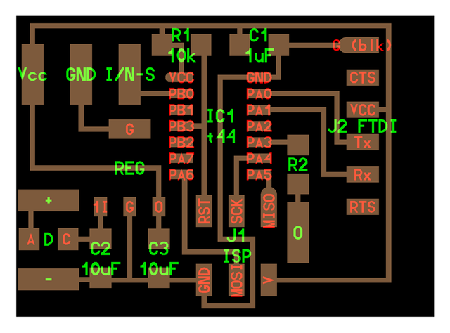
After the board design has finished, I started milling the FR1-paper by the SRM-20 milling cutter.
Soldering
Now it's time to start soldering the components. But firstly I have to collect the components for soldering.
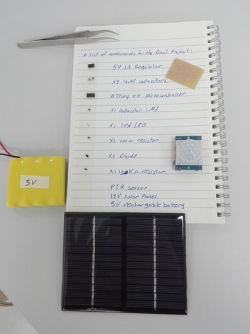
- 5V 1A regulator.. To regulate the input voltage came from the solar panel at 5V fixed output voltage; because the voltage out of the solar panel varies with amount of the solar radiation and for my circuit board I need 5V fixed output voltage as a power supply.
- x2 10uf capacitors.. To get smooth 5V DC output voltage (removing the ripple).
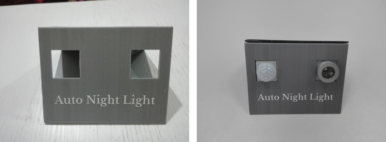
- ATtiny 44 microcontroller.. The microcontroller that will control the state of the light based on the state of the PIR sensor.
- x1 1uf capacitor.. Decoupling capacitor.
- x1 10kohm resistor.. Pull-Up resistor.
- LED.. represent the output light.
- x 100ohm resistor.. To limit the current that will be drawn by the LED.
- x1 Diode.. Protection diode; to protect the solar panel from the reversing of the power from the battery at night.
- PIR sensor.. Motion detector sensor.
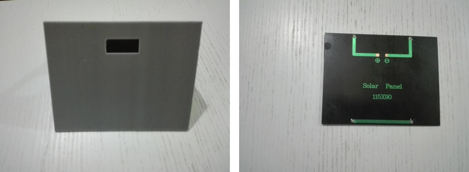
- 12V solar panel.. The main power supply; to charge the battery.
- 5V rechargeable battery.. To feed the circuit with electric power during night hours.
Then I started soldering based on the procedures that I have mentioned in the electronics production section.
Testing The Board
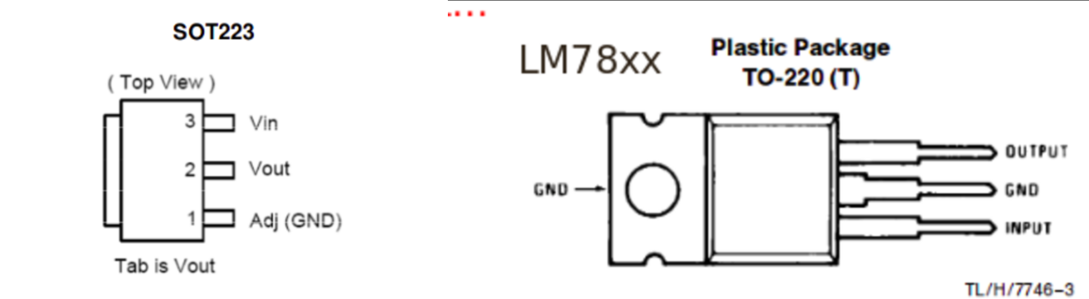
At first I tested the regulation section on the board to check the output voltage of the regulator if it is 5V and here was the first problem I faced on the final project. The regulator wasn't work as expected, then I opened the data sheet of the regulator and I found that the input, output and ground pins configuration on the data sheet differs from that which defined on the text code of the PCB. But now, it has been edited.
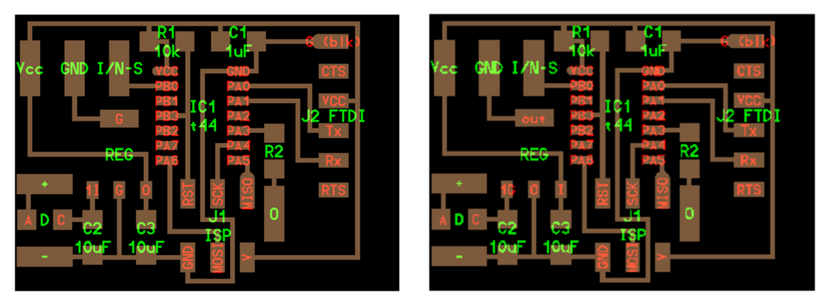
Also,because I have used the LM78xx regulators family before, I thought that all the regulators have the same pin configuration.
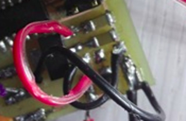
To solve this problem I used an art knife to cut some traces and then I soldered some wires in order to get the true connection of the regulator circuit. I used the black wires to connect the ground and the red wire to connect the input from the solar panel and for the output pin I soldered a trace from the output pin to the Vcc.
After that I re-tested the board to get a regulated 5V fixed output voltage.
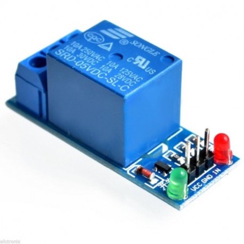
The other problem was that I have connected the output light directly with the microcontroller; because the microcontroller gives a power up to 40mA at 5V. Thus, the power of the lighting was very week. To solve this problem Mr. Fransisco recommended me to use a relay.
Programming
Before start programming I have to know the name of the pad which I have used it as an input as well as the name of the output pad. In my case I have chose the PB0 pin as input and PA3 pin as output. Also, I have to know if the input is digital or analog. In my case the input was PIR sensor which is a digital sensor. I have wrote the following program for my final project in order to automatically turn on the output light once the PIR sensor detects a motion.
#define setbit(register, bit) (register) |= (1 << bit)
#define clearbit(register, bit) (register) &= ~(1 << bit)
#define testbit(register, bit) (register) & (1 << bit)
#define F_CPU 1000000UL
#include <avr/io.h>
#include <util/delay.h>

int main (void)
{

setbit (DDRA, PA3);
clearbit (DDRB, PB0);
setbit (PORTB, PB0);


 while(1) {

          if (testbit (PINB, PB0)){
setbit (PORTA, PA3);
}else {
clearbit (PORTA, PA3);
          }
}
}
Mr. Fransisco asked me how I could make the sensor not to detect an animal ? My answer was to rotate the screw of one of the potentiometers which located on the PIR sensor circuit by a screw driver, in this way we could adjust the sensitivity of the sensor.
3D CAD
I have toke an idea about the final shape of the prototype from the cartoon prototype that I have already manually made. Then I wrote the dimensions of the final shape to sketch the design on a 3D CAD software.
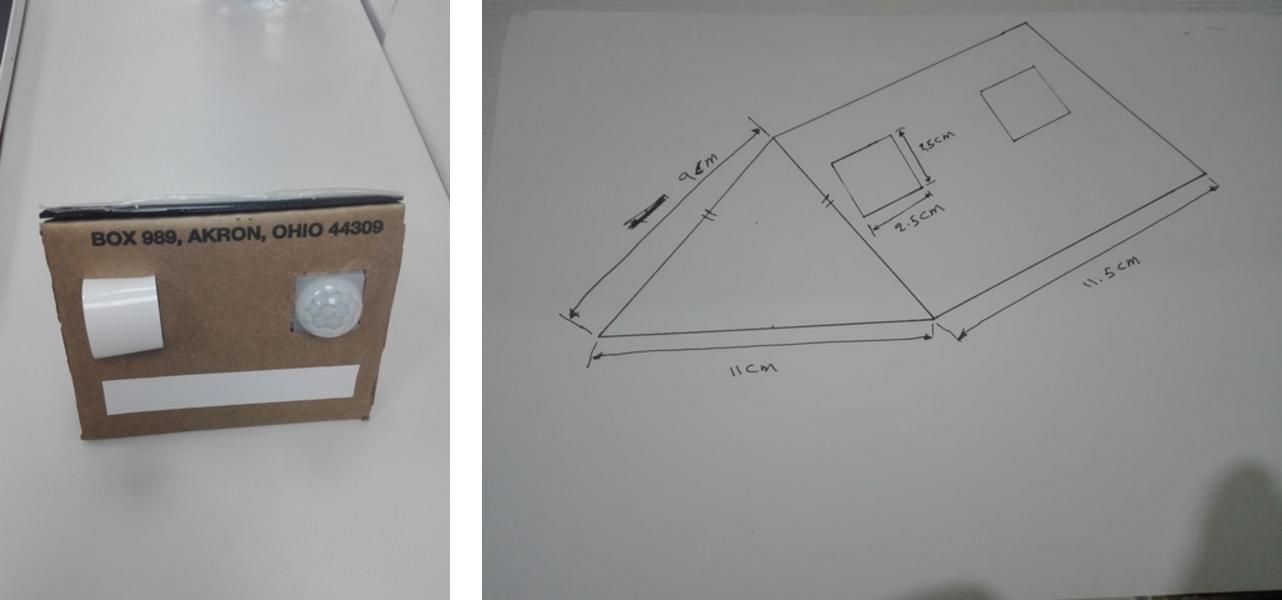
I used the freecad software to design the shape of the prototype.
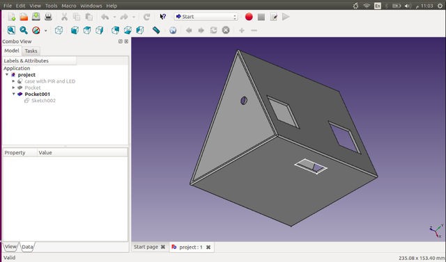
It is clear to see that the shape consist of three faces:
- Face (1).. For the sensor and the sticker.
- Face (2).. For the solar panel.
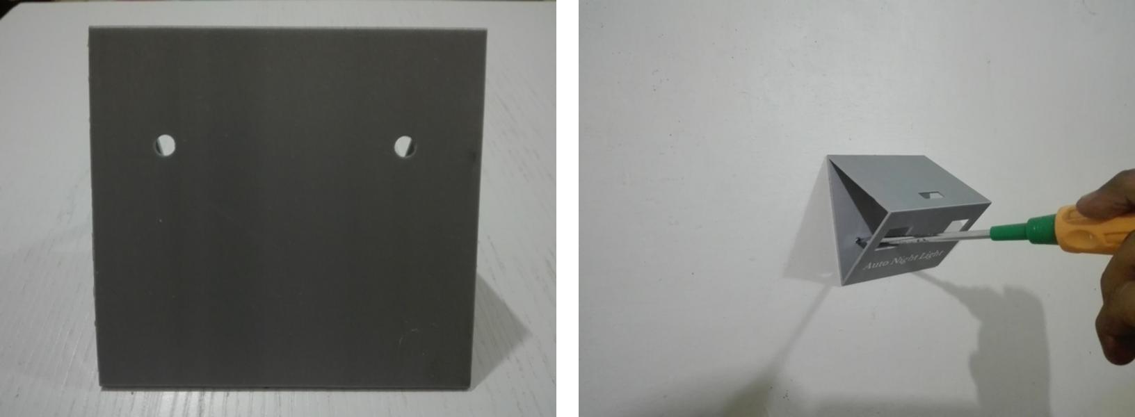
- Face (3).. For the screws.
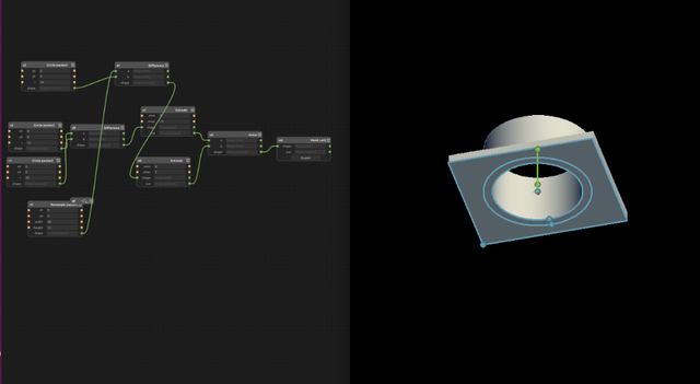
Also, I used the Antimony 3D CAD software to sketch the light holder.
Sticker
The commercial name of my project is Auto Night Light, I designed the sticker on the inkscape software.