-
Jiawen Gong authored
- /docs/assignments/week08.md
- /docs/images/week08/bracelet.jpg
Jiawen Gong authored- /docs/assignments/week08.md - /docs/images/week08/bracelet.jpg

08 WEARABLES
RESEARCH
I still have some things left unclear from the e-textiles week so some videos for myself to understand better the function of different components in electronics.
A transistor is a miniature semiconductor that regulates or controls current or voltage flow in addition amplifying and generating these electrical signals and acting as a switch/gate for them.
When working as an amplifier, a transistor transforms a small input current into a bigger output current. As a switch, it can be in one of two distinct states -- on or off -- to control the flow of electronic signals through an electrical circuit or electronic device.
How do you know which resistor to use:Types of Resistors and How To Choose One
ARDUINO
Arduino Language for coding.
ARDUINO BOARD
Arduino UNO is a low-cost, flexible, and easy-to-use programmable open-source microcontroller board that can be integrated into a variety of electronic projects. This board can be interfaced with other Arduino boards, Arduino shields, Raspberry Pi boards and can control relays, LEDs, servos, and motors as an output.

BREADBOARD
A breadboard is a plastic piece with conductive channels. It’s a solder-less way to connect wires, sensors, and devices to these ports to create prototypes, devices, and electronic circuits.

Breadboards are composed of 3 parts:
-
Horizontal Rows (yellow and green lines)
-
Vertical Columns
-
Power (red) /Ground (blue) Rails

The middle divider separates both sides. So if wire power and ground to one side of the breadboard, you will also need to power/ground the other side.

When wiring a breadboard, be sure that the wires lay flat and are attached neatly to the board. It is important to label wires that are attached to important sensors or actuators.

There are two sets of power rails that run along the edges of the breadboard. Rails are marked black/blue for ground (-) and red for power (+).
Each rail is independent of another, so you will have to connect the left positive rail to the right positive rail and the left negative rail to the right negative rail to supply power to both sides of the breadboard.
Once you’ve configured the power rails on the breadboard, you can use it to expand ports on a microcontroller, such as an Arduino by:
-
Connect a red wire from the Arduino Uno 5V to the breadboard + power rail.
-
Connect a black wire from the Arduino GND (ground) to the breadboard – ground rail.
Note: It is common to use red for POWER and black or blue for GROUND, but you don't have to use red and black wires. Whichever colors you use, be consistent so that you don’t mix the POWER and GROUND channels.
NOTES FROM EMMA'S TUTORIAL
If you connect an input you have to select the right pin depending on the sensor
Digital sensors:all the 10 pins are good
Analog sensors: can be connected only the A0/A5 pins
If you connect an output you have to select the right pin depending on how you want to control the device
Digital way: all the IO pins are good
Analog way: you can use only the PWM pins (~)
PROGRAMMING WITH ARDUINO UNO
CODE
int signal_pin = 3; //define the pin where the Arduino pin (signal) is connected

void setup() {

pinMode(signal_pin, OUTPUT); //define pin of the Led as an output
//pinMode(pin, OUTPUT);

//pinMode(pin, INPUT);
//pinMode(pin, INPUT_PULLUP);
}

void loop() {

digitalWrite(signal_pin, HIGH); //turn the Led on
//digitalWrite(pin, HIGH/LOW);
//HIGH -> 5V
 //LOW -> 0V ground
 delay(1000);                 //wait 1000millisecond
 digitalWrite(led_pin, LOW);  //turn off
 delay(1000);                 //wait 1000millisecond

}
ATTINY 85
ATtiny85 comes with a serial peripheral interface (SPI) that is mainly used for communication between the microcontroller and other peripheral devices such as SD cards, sensors, and shift registers.
I followed this tutorial to program my ATtiny: How to Program an Attiny85 From an Arduino Uno
CODE
// the setup function runs once when you press reset or power the board
void setup() {
  // initialize digital pin LED_BUILTIN as an output.
  pinMode(LED_BUILTIN, OUTPUT);
}

// the loop function runs over and over again forever
void loop() {
  digitalWrite(LED_BUILTIN, HIGH);  // turn the LED on (HIGH is the voltage level)
  delay(1000);                      // wait for a second
  digitalWrite(LED_BUILTIN, LOW);   // turn the LED off by making the voltage LOW
  delay(1000);                      // wait for a second
}
TESTING THE CIRCUIT BY CONNECTING IT TO A 3V BATTERY
SPEAKER
FABRICATION FILES
MOTION
DRIVER CIRCUIT
To follow Emma's tutorial on making a flipping wing we first prepared a power circuit.
A driver is a circuit or component used to control another circuit or component.They are usually used to regulate current flowing through a circuit or to control other factors such as other components and some other devices in the circuit. The term is often used, for example, for a specialized integrated circuit that controls high-power switches in switched-mode power converters.

TOOLS:
- A piece of thick paper or card
- Copper tape
- A piece of regular tape
- A MOSFET (ours was an IRF530)
- Soldering iron and solder
- Pliers to bend the legs of the MOSFET
If you don't have the materials to make the driver circuit on the breadboard, you can still build the circuit on the breadboard.

FLIPPING WING
MAKING A COIL

CONNECTING YOUR DRIVER TO ARDUINO

For a while my coil didn't work and it turned out that the aligator clips could't make enough contact with the wires. So I soldered the wires to another 2 pieces of metal for a better connection.
BOUNCING SPIRAL
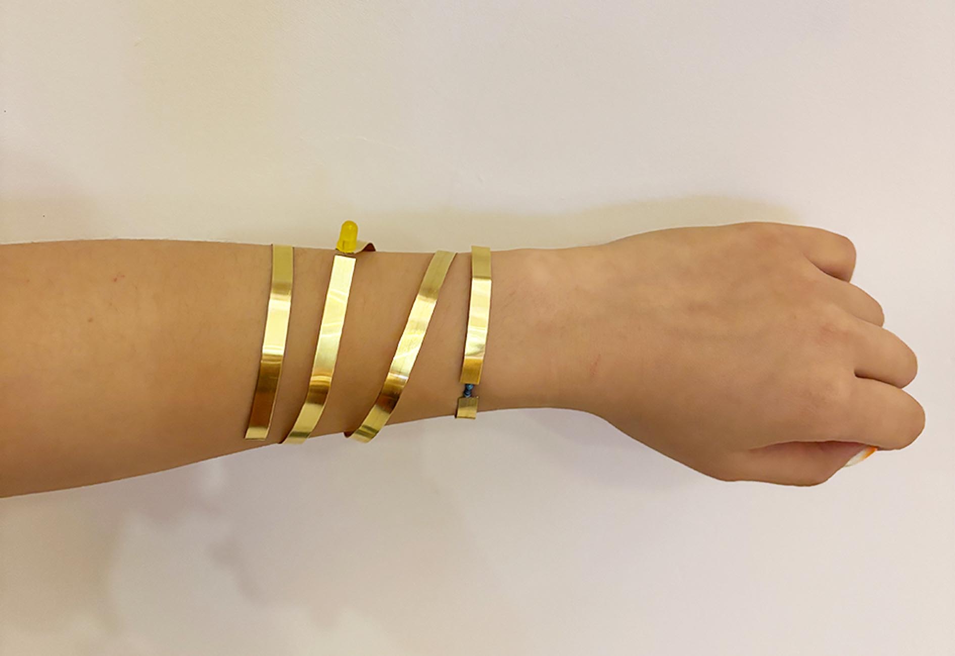
LED
I would like to make a copper bracelet with a blinkin led using the ATtiny that I programmed.