
9. Textile as scaffold
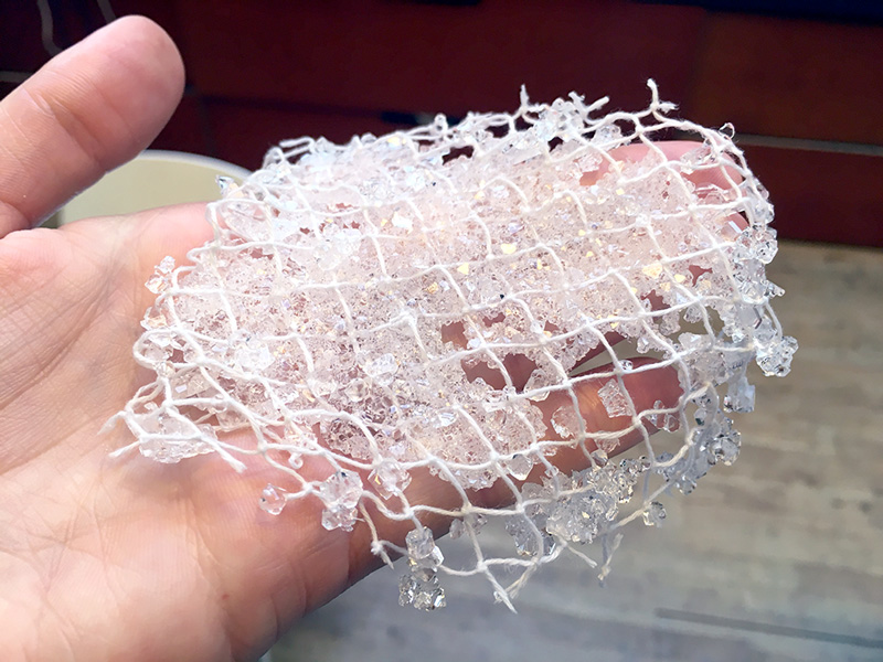 Never thought I'd be making crystal mesh, Loes Bogers, 2019
To Do
- Document the concept, 3D model of the piece and document the design process
- Make two samples with 2 out of the 5 techniques to make a prototype of a textile form: fabric formwork with casting crystalization wood-textile resin-textile leather molding or other
- Document the process from CAD to CAMM, document how to use the CNC mill and prototype your textile composite
- Upload your 3D model and CAMM file
- Document the 2 processes you have followed step by step from design to machine and hands-on making, materials you used, your mistakes, failures and achievements
- Use 3D modeling software to simulate your fabric deformation
##Results: crystals, composites and (hopefully) leather forming
 Conductive Alum Crystals on a pipe cleaner, tulle and conductive thread, made with Bare Conductive Ink, Loes Bogers & Frank Vloet, 2019
 Alum Crystals on velveteen, felt and loosely woven cheesecloth, Loes Bogers, 2019
 Leather molding on a 1.5 piece mold, Loes Bogers, 2019
##Growing crystals using yarn and textile
Sugar dissolves in hot water, but not in cold water. Dissolving: loose molecules spread evenly throughout because in hot water everything is dancing and agitated. When it cools down the molecules want to group together again, into a (partially) solid form. Crystals form better if they have a rough substrate to grow on, like a piece of thread or fabric. If you are using a dirty container or one with rough surfaces they can start growing on the jar.
The less you stir the water, the bigger the crystals can grow. Less agitation is better.
Alum crystal recipe
This is the source of the recipe we used.
- Alum
- Clean beaker or jar
- Saucer or shallow dish (a petri dish works, too)
- Pencil
- Fishing line
Process:
In one beaker, slowly add alum to 1/4 cup of very hot tap water, stirring to dissolve. Keep adding the alum until no more will dissolve: this is a saturated solution. Pour a little bit of this solution into a shallow dish or saucer and let it sit undisturbed overnight. Make sure you only pour the clear solution, not any of the undissolved material. You can pour it through a coffee filter if necessary.
 Alum crystal growing on felt, after 2-3 hours, Loes Bogers, 2019
Seed crystals vs. growing on a substrate
The recipe talks about making loose crystals, but we're growing them on different substrates. I used velour/velveteen, a loosely woven cheesecloth, and a piece of tulle that I hung in small jars or put in a shallow dish (petri dish).
The next day you should see small crystals growing in the dish. When they look to be a good size, carefully pour off the solution.
To grow seed crystals Don't add a substrate, but instead just let the solution sit. Make another saturated alum solution with about 1/2 cup of hot water. Pour the solution into a clean beaker or jar; avoid pouring any undissolved material.
Remove the biggest and best-looking of the small crystals from the saucer to use as your seed crystal.
Tie the fishing line to the seed crystal. This can be tricky; a pair of tweezers will help. If you need to, you can score a groove in the crystal to hold the line in place.
Tie the other end of the fishing line to a pencil, then set the pencil across the top of the jar so the seed crystal is suspended in the alum solution without touching the sides or bottom of the jar.
Note: if your seed crystal starts to dissolve, that means your solution isn’t saturated enough. Remove the seed quickly and add more alum to the solution, filtering off any undissolved particles.
Cover the jar with a paper towel to keep out the dust and let your crystal grow until you are happy with its size. When you take it out of the solution, set it on some plastic wrap to dry.
If you see other crystals growing in the jar, transfer the solution and seed crystal to another clean jar.
The small crystals that formed in the saucer grew because of nucleation. A few alum molecules found each other in the solution and joined together in a crystal pattern. Other alum molecules continued to join them until enough molecules gathered to become a visible crystalline solid. (Chemists call that a crystal “falling out of” the solution.) If you left these crystals in the solution they would continue to grow, but they wouldn’t get very big because they would all be competing for the remaining alum molecules in the solution. Instead, you took one crystal and used it as the only nucleation site in the solution. It was the primary site for the alum molecules to join together, so the crystal could grow quite large.
Conductive crystals
Frank and I made a few samples to create conductive crystals based on this recipe from EJTECH he found. They made some beautiful examples that they then used as capacative touch sensors for different applications.
- 1x Bare Electric Paint 50ml jar
- Boiling water
- Alum (or the same amount of borax)
- Fishing line
- Wooden stick
- Substrates like textiles/yarns/pipecleaners
The Bare Conductive paint we used was a bit old but heating it up and diluting helped dissolve everything anyway. We used tulle, pipecleaner stick and conductive thread for these samples.
 Frank pouring the alum solution through a funnel, Loes Bogers, 2019
Boil the water and add 100g of alum. Stir until super saturated and the powder is no longer dissolving. Add 1-2 teaspoons of Electric Paint (amount changes the resistance of the crystal!) and stir. Crystals form bigger when it cools down slower.
Wait 12 hours, take out the crystal, reheat the solution and add 3-4 more tablespoons of alum to saturate it more. Wait for it to cool down before putting the crystal back in or you might dissolve it. You basically give it more food to grow.
Wait another 12 hours and take it out. Continue the 12 hour cycle replenishing the solution with alum depending on how big you want the crystals to grow.
Threading tulle with conductive yarn
We laced the tulle with some conductive yarn to see if this makes it easier to solder the crystal/sensor to a circuit.
Capacitive touch test
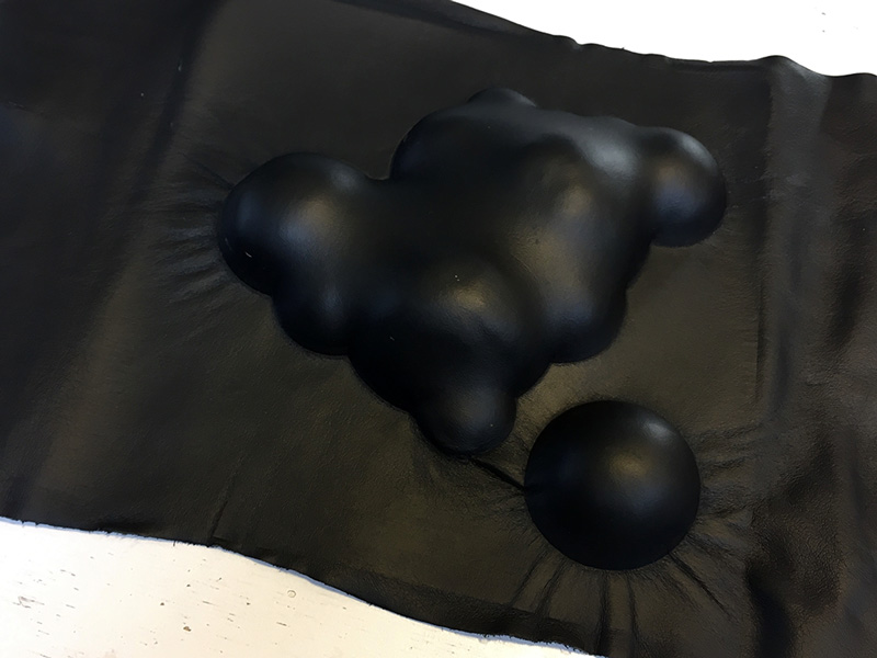
I tested the black alum diamonds by connecting them to a Bare Conductive Touch board, a dev board with capacitive touch sensing built-in. So I could see immediately if touching these crystals could trigger a response in a circuit. The big ones were perfect! The small mesh is triggered only when you touch the ones that sit on the conductive thread. See below.
Creating a swatch for the capacative crystal
I made a swatch using this crystal in week 10! You can take a look at the documentation of that week, which was about E-textiles and Electronics II.
##Bio-composite and Leather molding
I really loved one of the wooden molds Anastasia showed in her presentation on Cuir Bouilli, and thought it would be feasible for me to create a similar design using Grasshopper. So I did! This is the inspiration piece :) As I was playing around with it I kind of liked a less tidy piece, one that maybe looks a bit more like a tumor growing than a collection of neatly arranged spheres.
 "Esther hates PVC", mold for leather belt, Esther Perbandt, Loes Bogers, 2019
###Design Process
Approach
- do a very simple design, but one I can build from scatch in Grasshopper
- design something with a 2-part mold (never done before)
- go through motions of machine again. I worked with CNC milling machine a few times before for Fabacademy's Computer Controlled Machining Week, the Molding and Casting week and for the Composites week. But it's been a while, and designing for this machine can be quite complex I think.
- Figure out the process of leather molding (never done before), maybe even do a biocomposite as a bonus using the same mold :)
First designs
- I tried remaking a design from lecture that I liked in Grasshopper. When you know what you want it's much easier!
- Thinking in molds: adding a box. Searching for Boolean Union and Boolean Split in grasshopper (spoiler: it's SolidUnion and SolidDifference). On hindsight I didn't have to make the boxes this thick, it would only be extra milling time, so I chopped them off later.
- Thinking in molds: offset for the negative mold part to allow for material thickness. I pressed the leather I want to mold between a caliper, it measured
 Measuring the leather to determine offset of negative mold, Loes bogers, 2019
 First grasshopper design, made totally from scratch! Whoa. Loes Bogers, 2019
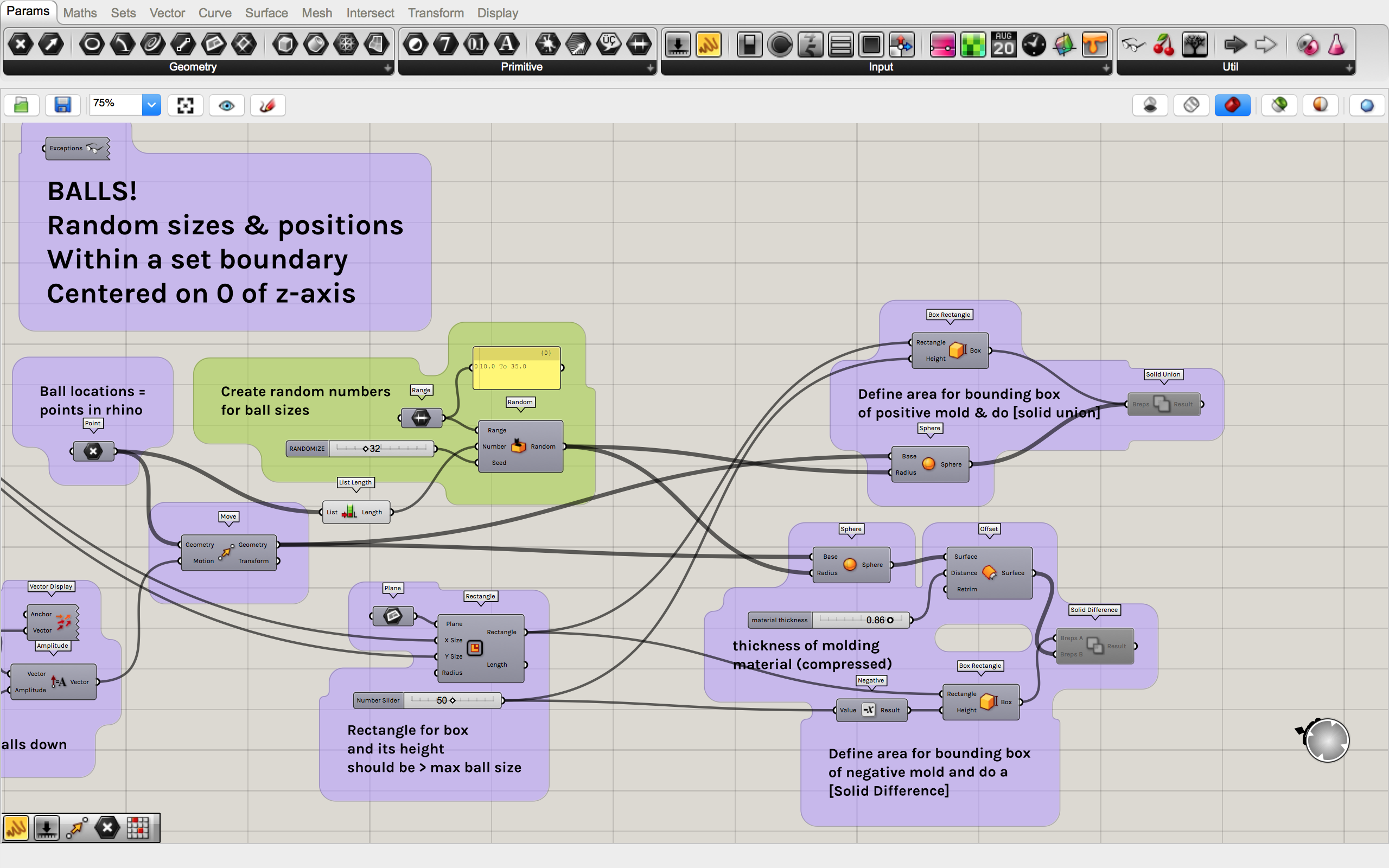
Grasshopper issues to be solved
As I started to elaborate the design I was struggling with very long waiting times and beach balls...I started adding panels to each output to see if they were giving the output I expected and if it matched the input it was going into.
When I baked I got like 10 shapes instead of one. And the random number generator was creating 144 values where I was expecting 7. So instead of directly connecting the output of the ball locations I put a [List Length] component after it and used that as input for the random generator. This fixed everything! Just one bake, and no more waiting.
Then I assessed a design I liked carefully with [DimAlign] in Rhino. I checked that the deep cavities were not too steep, and most corners and negative space between balls can be done with 5mm milling bit (2 flutes). I know it won't be perfectly sharp between the balls for the positive mold but I'm hoping that the negative mold part can compensate a bit for it.
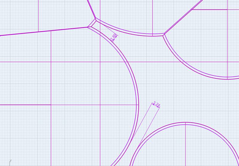 Unmillable parts of the design that needed to be changed, Loes Bogers, 2019.
I decided to populate manually using control points in Rhino, because had to adjust the positioning of the balls so the design could be milled with a 5mm milling bit. The spaces between the balls were often too small, and moving around was an easier way to control the position of the balls than the 2D populate component. The best one I could think of anyway.
I streamlined the "code" as much as I could, making things relative to one another where I could manage and where it made sense. I'm pretty happy with result, it works very fast now and I definitely feel a little more confident in Rhino/Grasshopper now. Small steps, easy does it.
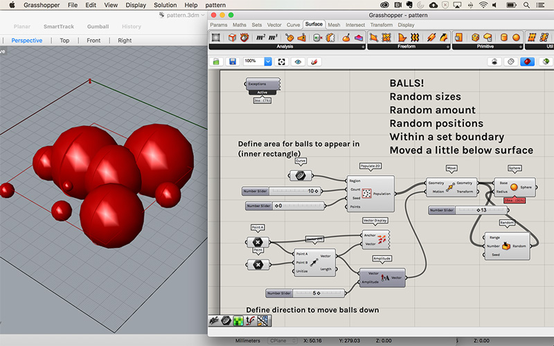
 Final design in Grasshopper, Loes Bogers, 2019
 Final design in Grasshopper, Loes Bogers, 2019
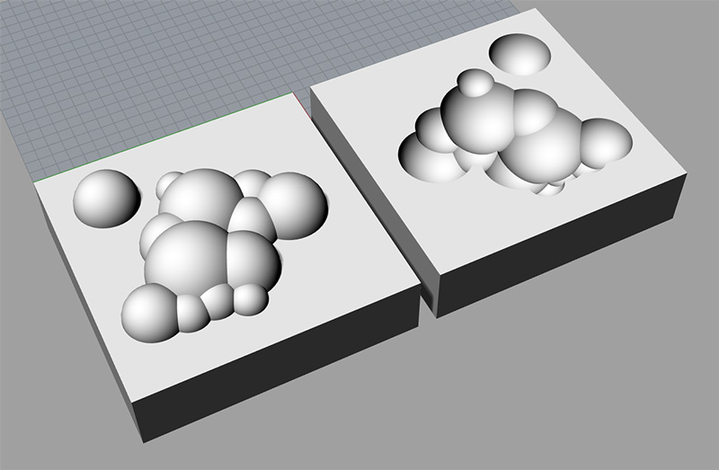 Design of the molds, Loes Bogers, 2019
And this is the Grasshopper file here
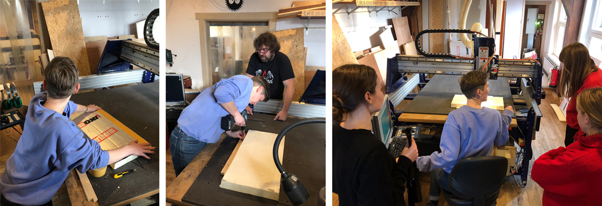
#Milling on the Shopbot
Lucky me, I had used the shopbot before and could use my notes from back then as we are still using the same machine and software at the lab! I documented it very thoroughly for the fabacademy CNC machining week, the molding and casting week and the composites week where I also made a composite with textile. But gosh it's so long ago! It was really nice to get a refresher with Henk and the other fabricademers.
I forgot you need to click the milling bit into the collet for example. And how to go through all the software steps. But the fear for the machine was engrained enough to still remember everything! Haha. I'm not afraid of the machine, just a little nervous when using it, but healthy nervous that makes me very sharp.
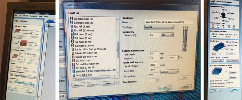
Settings
I'd prepared my design with a 5mm flat milling bit in mind and could use the settings that the lab manager, Henk had saved in the software's library. We changed the settings a little bit to work with high density foam, by increasing the stepover for the roughing toolpath, and increasing the feedrate. Because the foam is so soft, it can be milled a bit faster, milling a larger surface per toolpath, and going a bit faster that when you're milling wood for example.
 Thanks for the settings and the tutorial Henk, Loes Bogers, 2019
 **
**
The finishing toolpath
For the finishing toolpath we agreed on a 50% step over at a pass depth of 2mm foam. The basic settings are 18K RPM spindle speed (to be set on the machine itself), and a feed rate of 120. The machine estimated a 2 hour job which seemed quite long, and then we figured the feed rate could go up a lot for foam.
 Job setup for the roughing toolpath, Loes Bogers, 2019
The finishing toolpath
Here we kept most settings the same because I plan to use the same milling bit. Stepover is smaller here of course: 10%, with a path depth of 0.5mm I exported both toolpaths together.
 Job setup for the finishing toolpath, Loes Bogers, 2019
And this is a familiar step! The infamous zeroing of the machine using the metal bar. Always take a picture. Well here it is :) I ended up needing it too so that was a nice reminder.
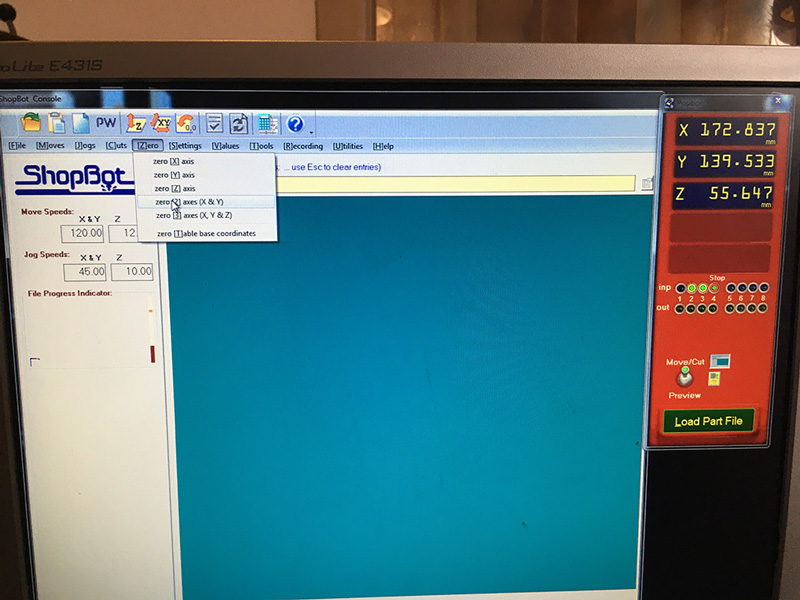 Zeroing the machine, Loes Bogers, 2019
After all this lenghty setup setup setup up, I could see the simulation of the toolpaths and prepare the machine for milling!
Simulation of the toolpaths the milling machine would run for me, Loes Bogers, 2019
I fastened the foam using double sided tape, and by screwing some wood strips to the sides. Let's start.
 Fastening the material, shot by Bea Sandini, 2019
Issues and solutions
During the last run of the roughing toolpath, the nut of the machine touched the surface of the foam on the edges, the tool depth was not enough to prevent this. Even though we thought we measured and calculated everything. The cavity ended up being too deep for the milling bit. Ouch! I paused the machine of course but there wasn't much I could do in the middle of a job. So Maud – who was interning at the lab – switched off the machine to prevent burning. We discussed if I could salvage the design, and because it was only doing the very last path, it was worth trying to do the finishing toolpath anyway, even though it hadn't totally finished the roughing. The soft foam would probably be cut away just fine. And it did! I had to export the finishing toolpath separately again, double checked the zeroes of the machine and ran the finishing path.
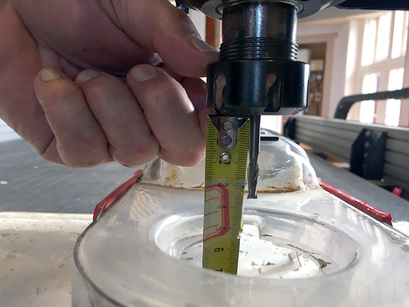 Tool depth of 3.5mm, Loes Bogers, 2019
 The burn that was made when the shopbot touched the foam during the job, Loes Bogers, 2019
What happened? In the job setup we sank the design lower into the material but did not add up that number to the milling depth we needed to reach. Easy mistake to make. Will remember for next time.
**
I solved this issue by cutting away the foam at the edges of the design by hand, before starting the finishing toolpath. This created space for the nut to do the milling without touching and burning the foam.
 Cutting away some of the surface to make space for the nut on the outer edges when milling the bottom layers, Loes Bogers, 2019
Skirt damaging the foam?
The skirt damaged the foam in a few places, leaving my balls a bit deformed. You can see in the image here how the edges of the passes are not straight, they're already rounded. The skirt passing over it time and time again does that. For these edges it's fine because they will go with the finishing toolpath anyway, but there was also some damage at the top
 Skirt brushing the design, Loes Bogers, 2019
Fastening, but not so fast
One corner of my foam started to come off of the bed a little bit. I'd fastened it with double sided tape (covered the entire surface) and screwed some pieces of wood on the sides to keep it in place but it still popped up. It wasn't a huge issue but the final piece had a few lines in it where it cut a part of a path deeper than the rest where to foam was higher in the air than the rest.
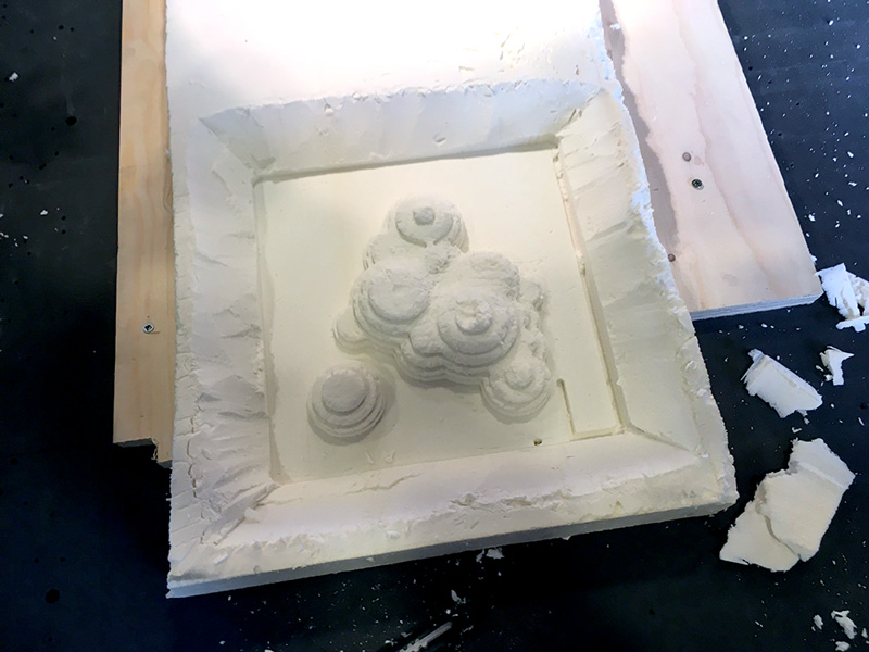
 But finally, finished snowballs. A bit damaged by the skirt. Note the deeper lines on the right side where to foam lifted a little, Loes Bogers, 2019
Due to time constraints this week, I just made the positive mold to try out some techniques. Unfortunately there was no more machine time left after all our students did their milling so I couldn't make the negative mold. Instead, I laser cut the outline of the shapes from a piece of acrylic that I could use the clamp down the leather to push it into the corners.
##Gcode study
I also tried to figure out a little bit using this reference document. Below is a snippet from the first part of the Gcode that is actually quite readable if you look up the abbreviations. I annotated it to understand a little. Because I was missing only one path of the roughing, we were wondering if I could just change the gcode file to just run the last few lines. I didn't do it because, well, not sure what the hell I'd be doing, but wanted to know if it would be possible. With a bit of studying it should be doable I think.
'----------------------------------------------------------------
'SHOPBOT ROUTER FILE IN MM
'GENERATED BY PARTWorks

// Dimensions I put in for the material

'Minimum extent in X = 0.000 Minimum extent in Y = 0.000 Minimum extent in Z = -50.000
'Maximum extent in X = 300.000 Maximum extent in Y = 300.000 Maximum extent in Z = 0.000

// 300x300 and sunk down 5 mm

'Length of material in X = 300.000
'Length of material in Y = 300.000
'Depth of material in Z = 50.000
'Home X = 0.000000 Home Y = 0.000000 Home Z = 2.000000
'Rapid clearance gap or Safe Z = 2.000
'UNITS:MM
'
IF %(25)=0 THEN GOTO UNIT_ERROR	'check to see software is set to standard
SA  'Set program to absolute coordinate mode
CN, 90
'New Path

/// Roughing toolpath using the toolsettings from Henk

'Toolpath Name = Roughing Toolpath - Top
'Tool Name   = 5mm flat 2 flutes (henk-fabacademy2018)

// Modifications we made to those settings: pass depth and stepover

&PWSafeZ = 2.000
&PWMaterial = 50.000
'&ToolName = "5mm flat 2 flutes (henk-fabacademy2018)"
&Tool =1                    'Jog Z axis to safe height
C9
TR,18000
C6                   'Return tool to home in x and y
PAUSE 2
'

// MS = Move Speed Set (we set feedrate to 120 mm/s)
MS,119.5,39.8

// JZ = Jog on the Z-axis (move up or down)
JZ,2.000000

// J2 = Jog 2 dimensions (move to a point on x & y axis)
J2,0.000000,0.000000

// J3 = Jog 3 dimensions (move to new point on x,y and z axis
J3,254.689957,251.729401,2.000000

// M3 = Move on 3 dimensions using the milling speed
M3,254.689957,251.729401,-6.000000
M3,254.689957,48.270596,-6.000000

[...]
And here's the shopbot file.
#Lay-up
##Bio-composite with silk chiffon
I wanted to try the leather molding but found out that without a vacuum pump you need to manually massage it until dry so I had to wait until the next day (it was 4PM when I found out). So I also prepared a bioresin to try a one-layerd silk-bioresin composite that I could let dry overnight. Tomorrow I'll try to do the leather molding.
Preparing the mold
I prepared the mold by covering it tightly with cling film. To help make it tight I stuck the mold to a cardboard box, this was a bad idea because my vacuum bag totally did not keep the vacuum and it was probably because of this move. I'm really wondering if the vacuum will be strong enough to push the foil down into the cavities but we'll see. I rubbed it with vaseline as a release agent
 Covering the base with plastic film, Loes Bogers, 2019
I then prepared all the other layers: silk chiffon (1 layer) for the composite itself, a piece of cling film that I perforated with a pattern rolling tool with the pins
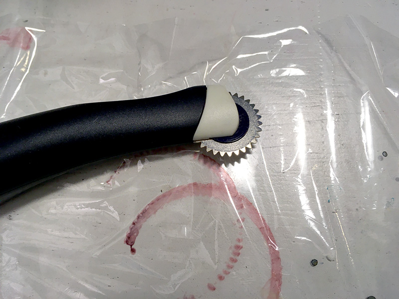 Perforating cling film, Loes Bogers, 2019
Tool: high density foam mold Fibre: Silk chiffon Mold release agent: vaseline Release fabric: cling film Perforated release film: cling film, perforated by hand Bleeder: a piece of cotton canvas Breather: a cotton mesh Vacuum bag: a vacuum bag to store clothing items in
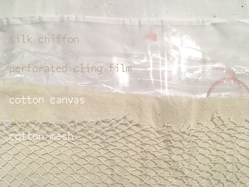 The different layers, Loes Bogers, 2019