
Final Project
My project will be a vegetable washing machine
Research
Goal is to create a kitchen appliance that can wash and dry greens and other vegetables via a pre set cycle both saving time (and potentially water)
Project description
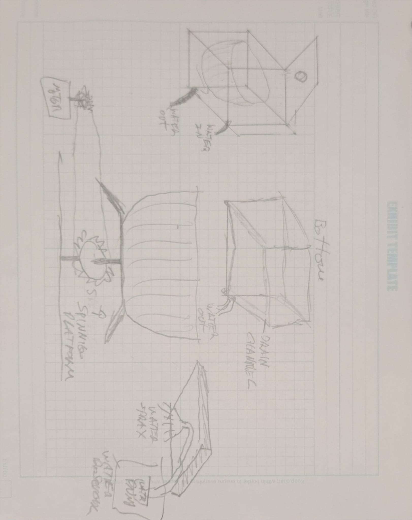
Here is a first cut at the base:
There are 4 main parts to the appliance
-
Water reservoir
-
Main container (Wash basin)- base is designed to have a gravity fed drain
-
Lid with build in sprinkler
-
Vegetable holding bowel that sites in the Wash basin and spins to dry
There are 2 Motor/pump used
-
Water pump to move water from reservoir to sprinkler head
-
Motor to spin Vegetable bowel
There are 2 potential sensors
-
Lid sensor - stop operation if lid is open mid cycle
-
Water level sensor to alert if reservoir is empty
Microcontroller usage
-
Control sequencing of pumps / motors
-
Interrupt operation if sensor is triggered
-
Manage GUI
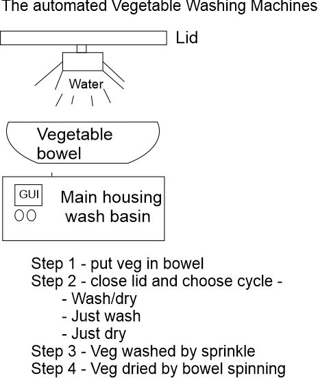
GUI
-
Based display and buttons
-
Allow user to start cycle
-
Wash only
-
Dry only
-
Wash/dry
- Announce alerts (ready/water empty/finished)
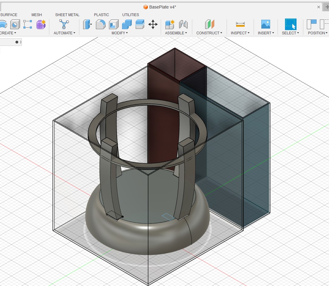
Here is a another view of the merging design
Align parts to Fab Academy weekly topics
| Weekly topics | Parts |
|---|---|
| Computer controlled cutting | Outbox / wash basin holder |
| Electronics production | Controller, motor ESC, Sensors |
| 3D Scanning and printing | Motor housing, water connectors, sprinkler head, sproket/chain for motor drive |
| Electronics design | sensors / controller board / Motor ESC |
| Computer controlled machining | Controller board |
| Embedded programming | Cycle design / User input |
| Molding and casting | Drain / Spinning plate |
| Input devices | GUI buttons / Sensors |
| Output devices | Screen |
Key component breakdown
Outer box - Plexiglass
Wash basin holder - Plexiglass / 3d print
Water reservoir - molding / buying
Electronic housing - 3D print
spinner mechanism - 3D print
Bowel - Molding / casting
Lid - 3D Print
Water pump / sprinkler mechanism - 3D print / electronics
Sensors - 1) Lid sensor 2) Water level sensor
Controller board -
Display/Buttons
Water connections - 3 Print or buy
2D and 3D Modeling
First I set up some user parameters I will use in sizing the spinning plate and it base

Now I made a round leg for the plate to sit on

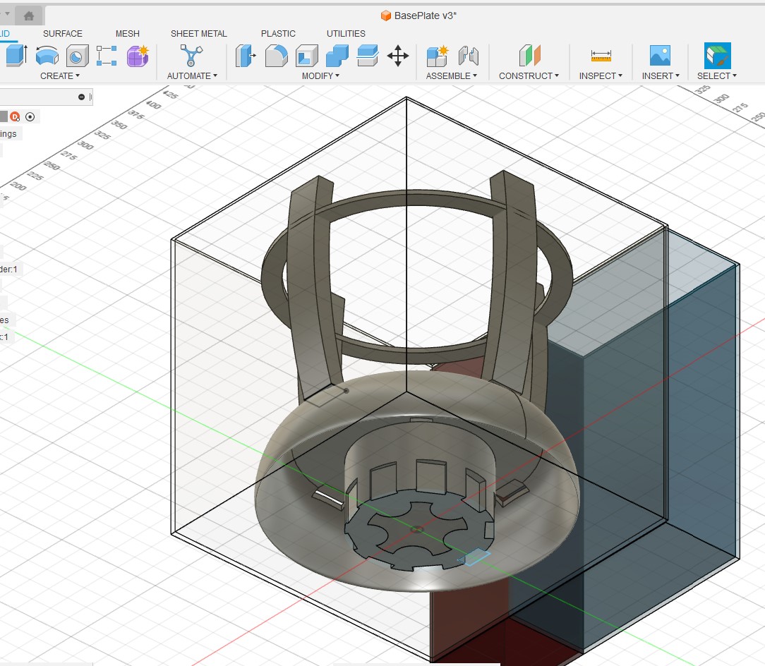
To create the shape of the base I will create a new sketch on the top of the base leg. I then create a circle and replicate it using the circular pattern tool followed but a cut.


I then sketched on top again and created a circle to create the plate itself

Here I made a mistake as I did not select the whole plate and where the handy timeline tool come into play

And we are back on track. I wanted to create a downward facing lip in order to provide some water protection for the spinning mechanism during the dry cycle.
To do this I am going to draw a sketch of the lip and have it rotate around the plate center axis
Start with sketch

Then used the revolve to create the lip and set it to join the plate base.

and there you go a first cut at the base plate

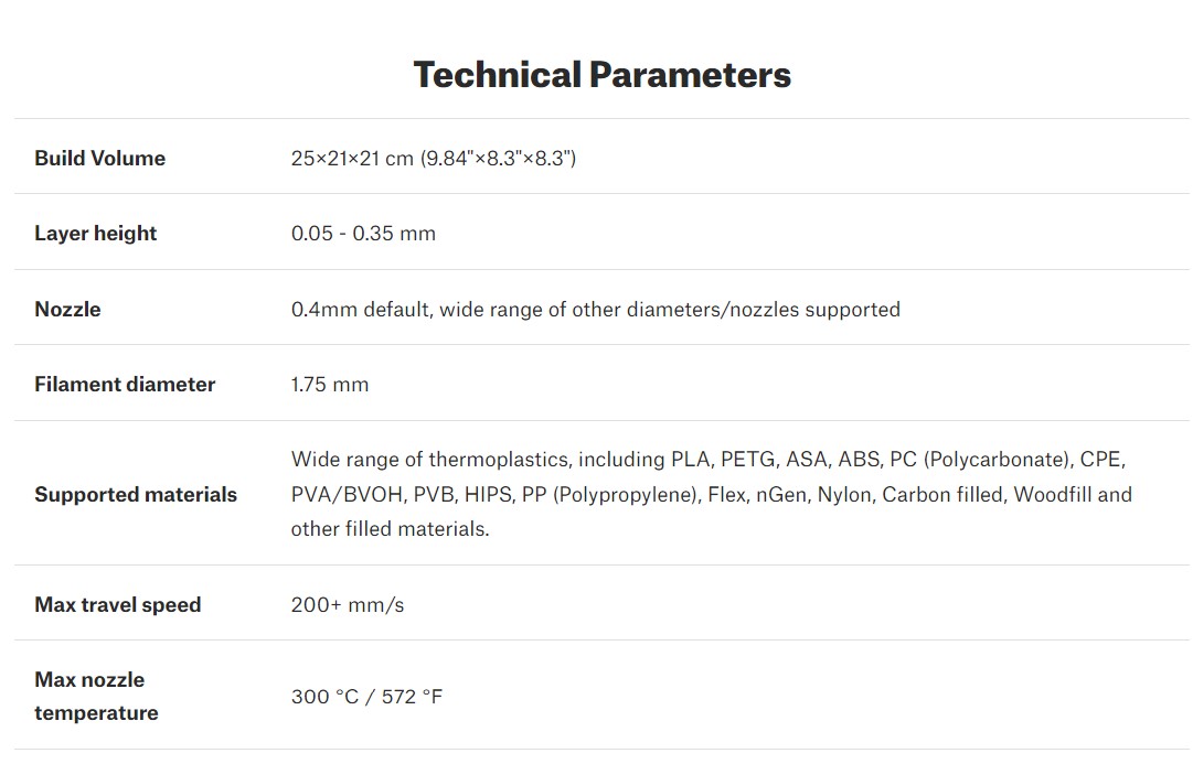
3D printing the plate
I started off by printing a test model aprox 50 of the size
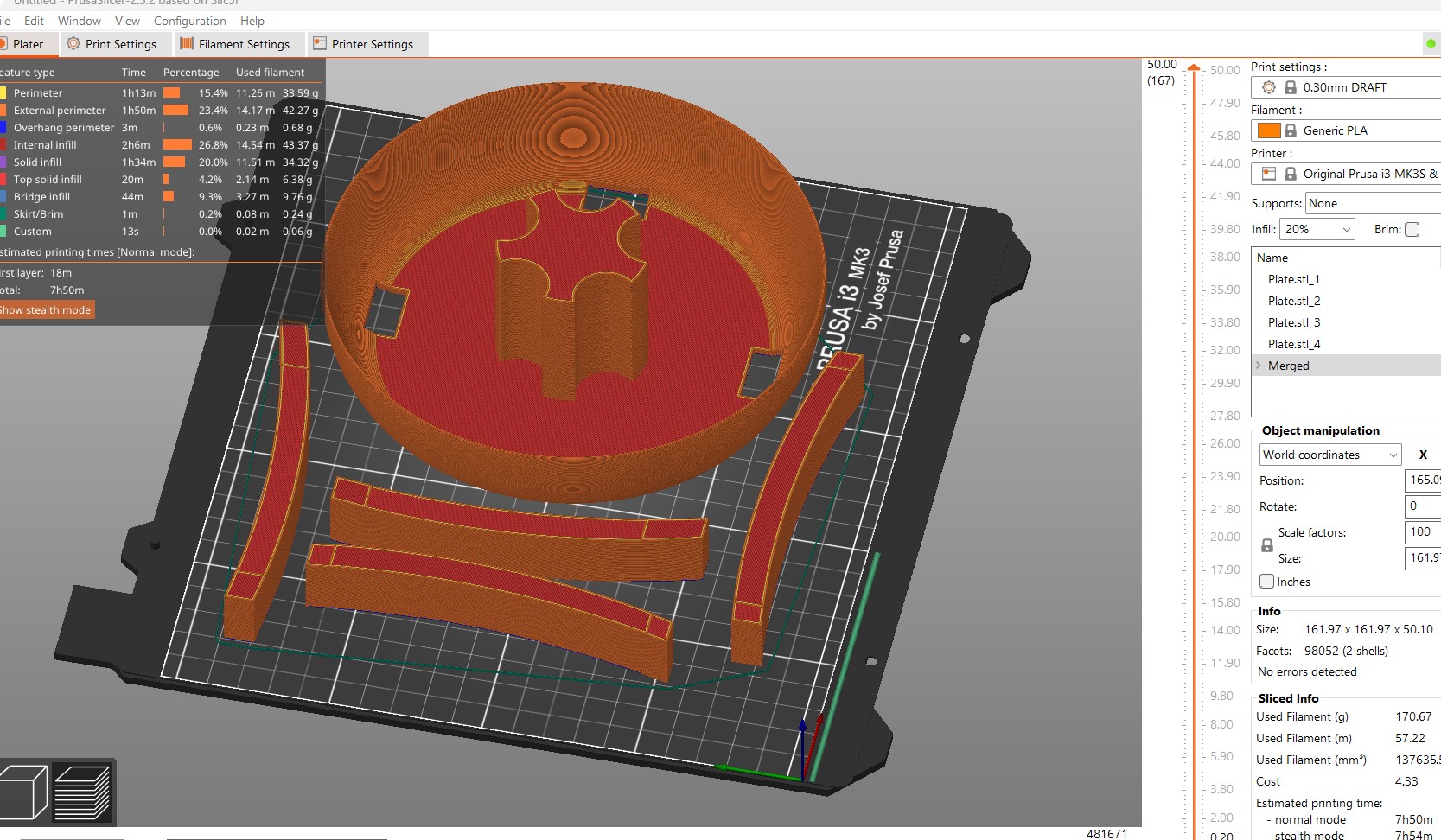
After 5 hours, here it is:
When I put it up to the salad spinner bowel I have it seemed to me that the overall size of the machine
can be much smaller then I originaly planned.
I think a good approach is the max the size of the plat I can print on the MK3S
The original size had a 320mm diameter but I am going to resize it to a 200mm diameter
I used the scale command leaving the Z as is and scaling the X and Y to 62.5% of the original

and here we have it
In addition I found a model of the motor I am planning to use on GrabCad

This an out runner and I would like to cut its shape into the bottom of the spinner to test a direct drive


Code basic set up
To keep this week in sync with my final project I decided to test a set up for the basic VMS functionality replacing the water pump and motor with LED and the sensors with buttons.
Here is the functionality I was aiming for:
| Button | Label | FUnctionality |
|---|---|---|
| Button 1 | Wash cycle | 1. Check Lid / Water sensor -> 2. Turn on Water pump and motor for a set time |
| Button 2 | Dry cycle | 1. Check Lid -> 2. Turn on motor for a set time |
| Button 3 | Total cycle | 1. Run Wash cycle -> 2. Run Dry cycle |
| Sensors | If either sensor is triggered then stop and turn on error LED |
Here is my updated code:
// Define the pin numbers for the sensors and actuators
const int LED_PIN = 7;
const int WASH_BUTTON_PIN = 11;
const int DRY_BUTTON_PIN = 10;
const int FULL_BUTTON_PIN = 9;
const int WATER_SENSOR_PIN = 2;
const int LID_SENSOR_PIN = 3;
const int DRUM_PIN = 4;
const int WATER_PUMP_PIN = 5;
void setup() {
Serial.begin(9600);
pinMode(LED_PIN, OUTPUT);
pinMode(WASH_BUTTON_PIN, INPUT);
pinMode(DRY_BUTTON_PIN, INPUT);
pinMode(FULL_BUTTON_PIN, INPUT);
pinMode(WATER_SENSOR_PIN, INPUT);
pinMode(LID_SENSOR_PIN, INPUT);
pinMode(DRUM_PIN, OUTPUT);
pinMode(WATER_PUMP_PIN, OUTPUT);
}
void loop() {
// Wait for the wash button press
if (digitalRead(WASH_BUTTON_PIN) == HIGH) {
// Check the water level and lid status
if (digitalRead(WATER_SENSOR_PIN) == LOW && digitalRead(LID_SENSOR_PIN) == LOW) {
// Start the wash cycle
digitalWrite(DRUM_PIN, HIGH);
digitalWrite(WATER_PUMP_PIN, HIGH);
delay(600);
digitalWrite(DRUM_PIN, LOW);
digitalWrite(WATER_PUMP_PIN, LOW);
delay(400);
digitalWrite(WATER_PUMP_PIN, HIGH);
delay(400);
digitalWrite(WATER_PUMP_PIN, LOW);
} else {
Serial.println("Not enough water or lid is open.");
digitalWrite(LED_PIN, HIGH);
}
}
// Wait for the dry button press
if (digitalRead(DRY_BUTTON_PIN) == HIGH) {
// Start the slow spin
if (digitalRead(LID_SENSOR_PIN) == LOW) {
digitalWrite(DRUM_PIN, HIGH);
delay(600);
// Start the fast spin
digitalWrite(DRUM_PIN, LOW);
delay(300);
digitalWrite(DRUM_PIN, HIGH);
delay(300);
digitalWrite(DRUM_PIN, LOW);
} else {
Serial.println("lid is open.");
digitalWrite(LED_PIN, HIGH);
}
}
// Wait for the full cycle button press
if (digitalRead(FULL_BUTTON_PIN) == HIGH) {
// Perform the wash cycle
if (digitalRead(WATER_SENSOR_PIN) == LOW && digitalRead(LID_SENSOR_PIN) == LOW) {
// Start the wash cycle
digitalWrite(DRUM_PIN, HIGH);
digitalWrite(WATER_PUMP_PIN, HIGH);
delay(600);
digitalWrite(DRUM_PIN, LOW);
digitalWrite(WATER_PUMP_PIN, LOW);
delay(400);
digitalWrite(WATER_PUMP_PIN, HIGH);
delay(400);
digitalWrite(WATER_PUMP_PIN, LOW);
} else {
Serial.println("Not enough water or lid is open.");
digitalWrite(LED_PIN, HIGH);
return;
}
// Perform the dry cycle
// Start the slow spin
if (digitalRead(LID_SENSOR_PIN) == LOW) {
digitalWrite(DRUM_PIN, HIGH);
delay(200);
// Start the fast spin
digitalWrite(DRUM_PIN, HIGH);
delay(200);
digitalWrite(DRUM_PIN, LOW);
delay(200);
digitalWrite(DRUM_PIN, HIGH);
delay(100);
digitalWrite(DRUM_PIN, LOW);
} else {
Serial.println("Not enough water or lid is open.");
digitalWrite(LED_PIN, HIGH);
return;
}
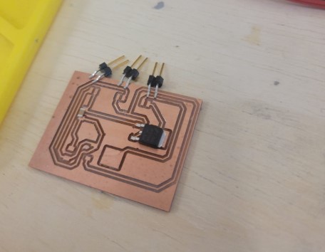
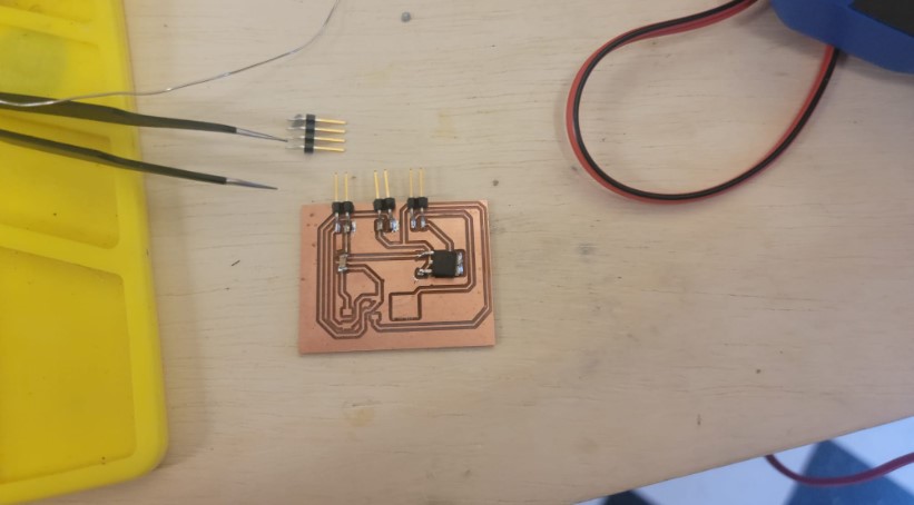
}}Here is the basic circuit I am planning
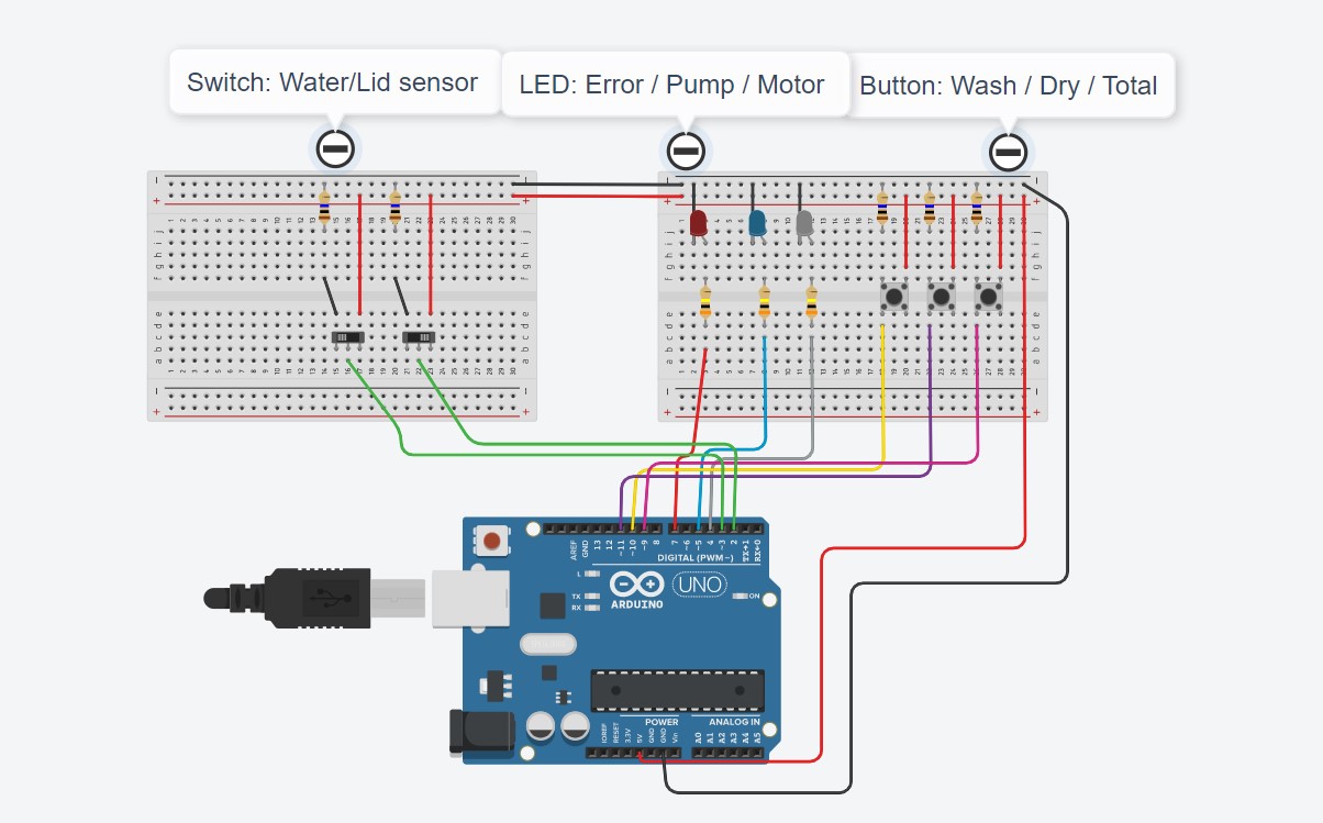
I followed this diagram (except for the different colored wires) and it went pretty smoothly
Here is the one I built in action:
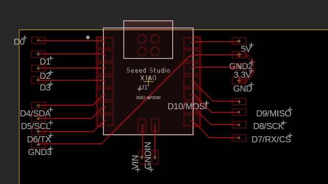
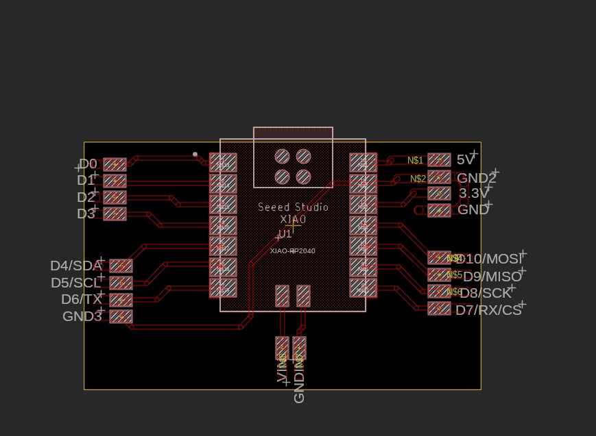
New board - Moving to RO2040
After a while I decided to move to a working iwht th eRP2040
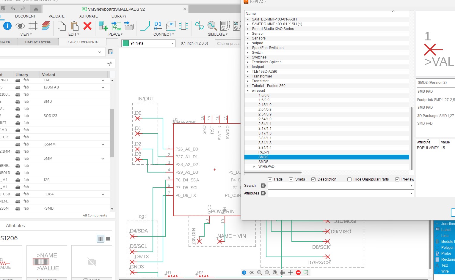
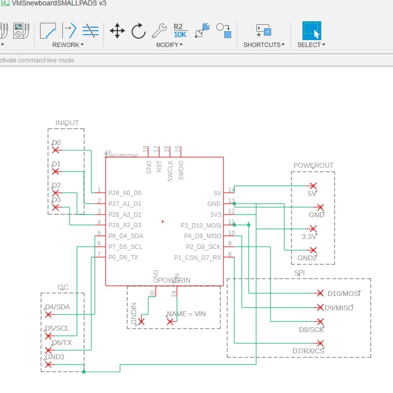
I am going to follow the same break out board design and so I started to work on a schematic. I am planning to use 4 pin wire to board connectors and 2 pin for the power as an alternative to the USBC.
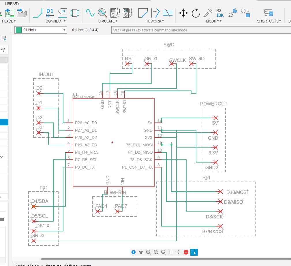
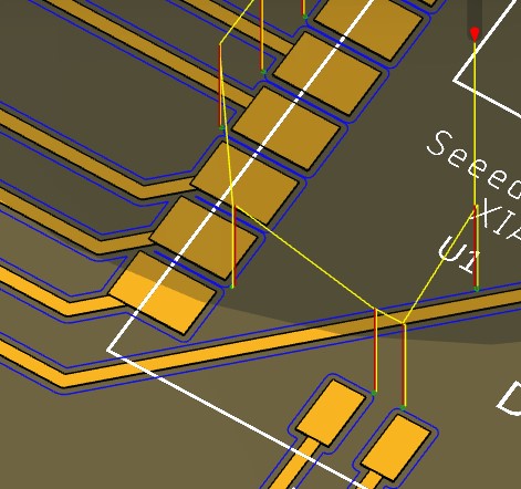
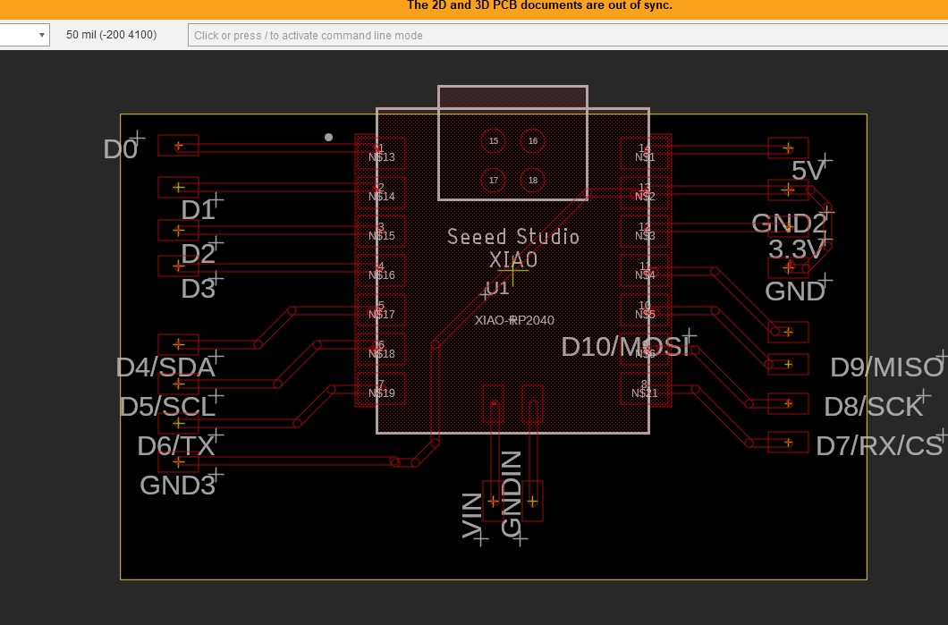
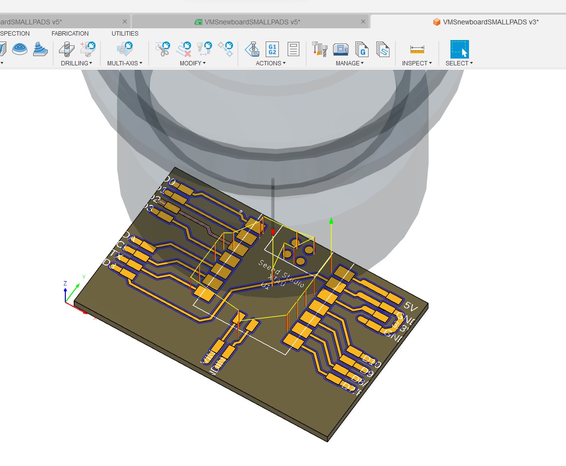
I have the 2D Board set up
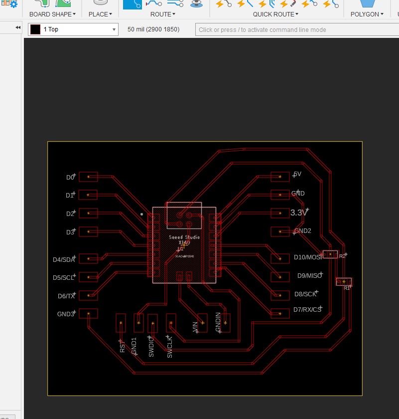
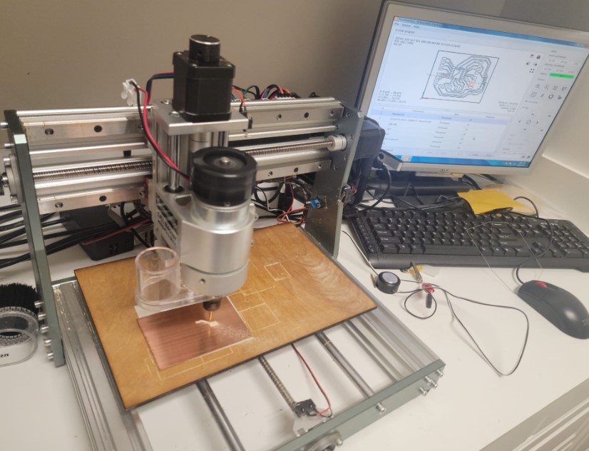
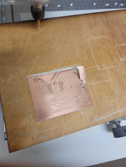
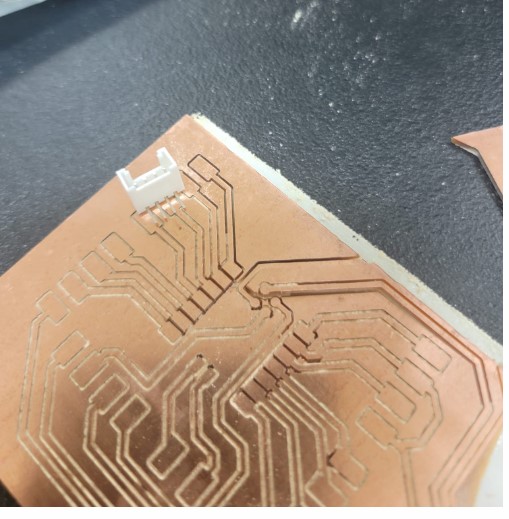
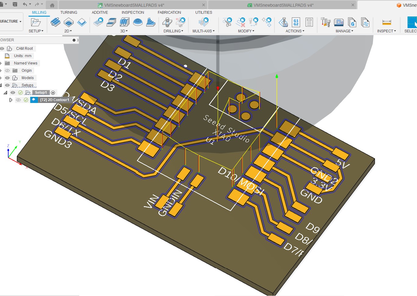
Now we are ready to mill
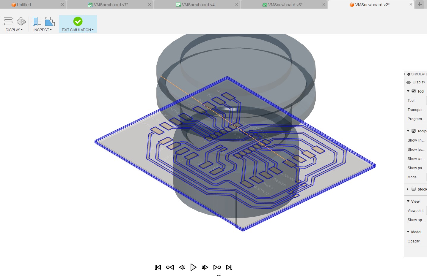
Here we are in action
Spinning Motor set up
For my vegetable washing machine I purchased 3 parts:
-
12-24V power supply
-
12-24V / 80W DC Motor
-
12-24V Motor ESC
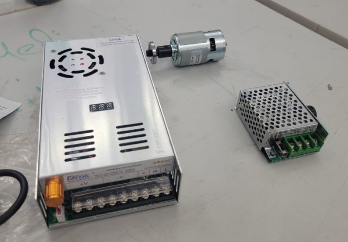
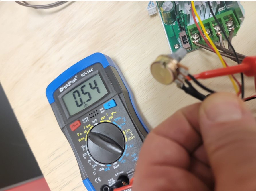
The ESC is controlled by a Potentiometer and once I got them connected they all worked well together. When I turned the knob the motor speed changed.
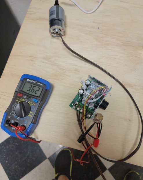
I want to be able to control the ESC with the microcontroller so I can adjust the speed for the wash and dry cycles.
First I need to understand how the Potentiometer works with the ESC. There is a plug with power and ground on either side the middle wire voltage change based on the potentiometer position ranging from 0.5V to 3.6V.
I was not sure how to approach this, my initial plan was to use 2 resistors and some relays to switch between 2 speeds. After reviewing Dr. Gershenfeld class and reflecting on the transistor discussion I came up with the idea of used a transistor to replace the potentiometer and a capacitor to smooth out the control signal from the microcontroller.
I ran this by our local instructor Mr. Dubick and my classmate Adam Durrett that have strong electronics background and they agreed it should work!!!
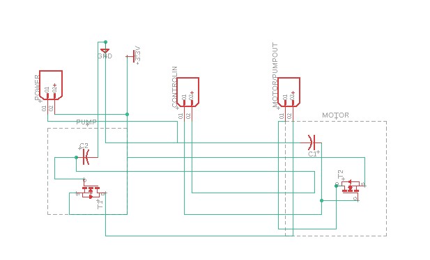
Motor control circuit design
I decided the set up the board to control both the motor the spin the Vesgtable Basket as well as the Water pump even though my focus this week was on the motor.
For each I would have a control signal come in from the micro controller on the main board. I would change the frequency of the signal the change the speed, putting a capacitor on the line would smooth it and would replace the line in with the potentiometer.
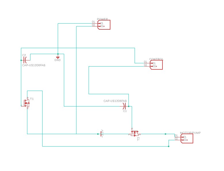
Not to get things a bit more organized. It is a relatively simple circuit
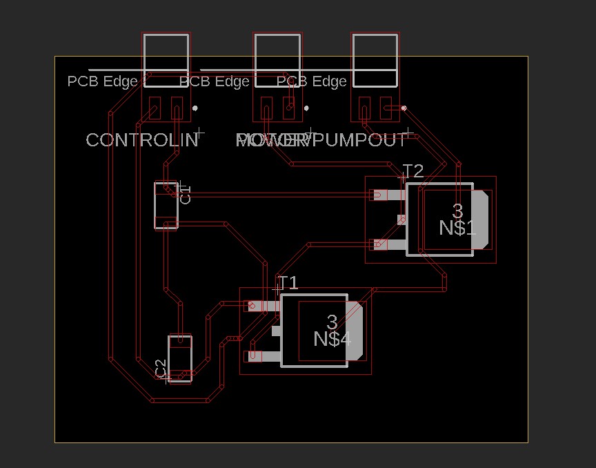
Not pushed it to the 2B Board and started tracing
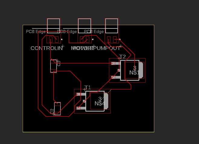
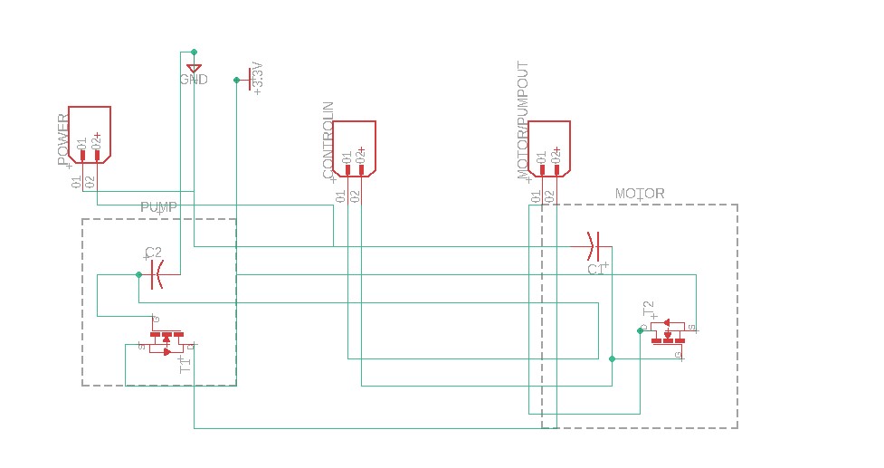
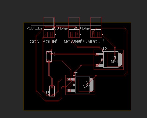
Motor control PCB design
Pushed to the 3D board get ready to mill
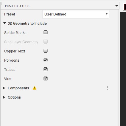
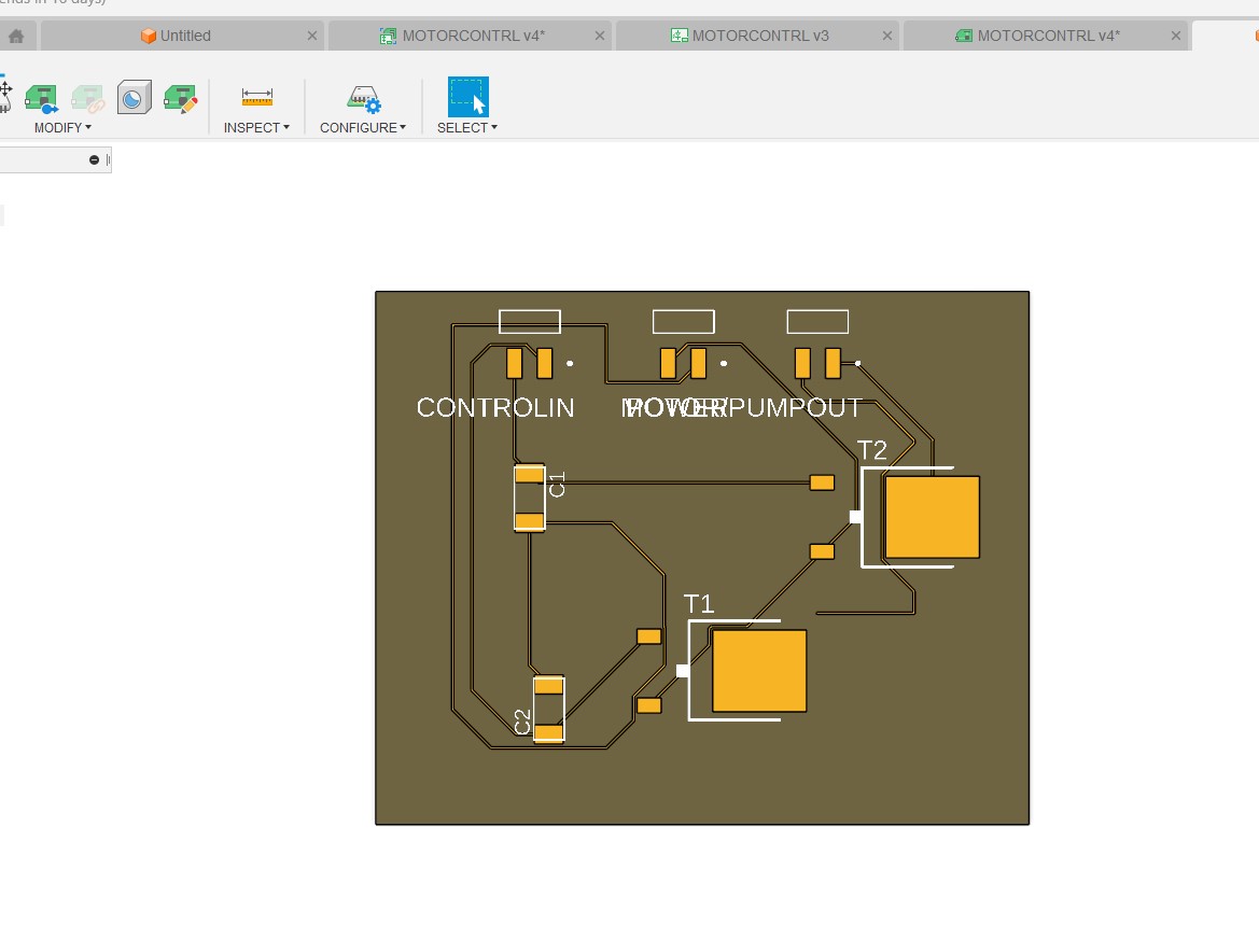
When I reviewing the milling it was very tight due to the tracing.
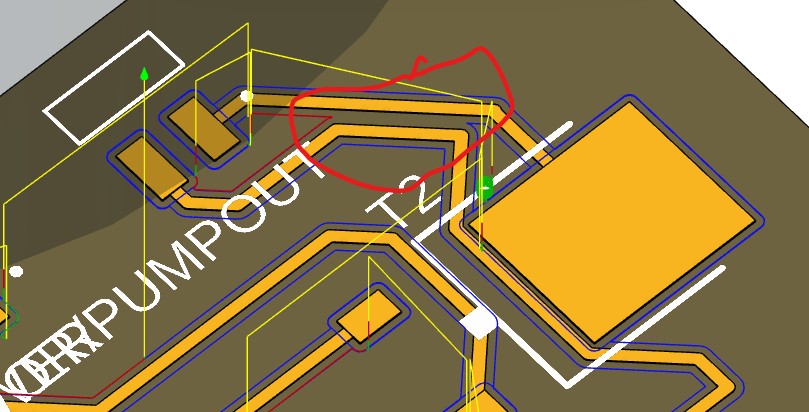
I reviewed the connectors and saw that by switch a few things around I could simplify the tracing and provide more space between traces to make for easier milling
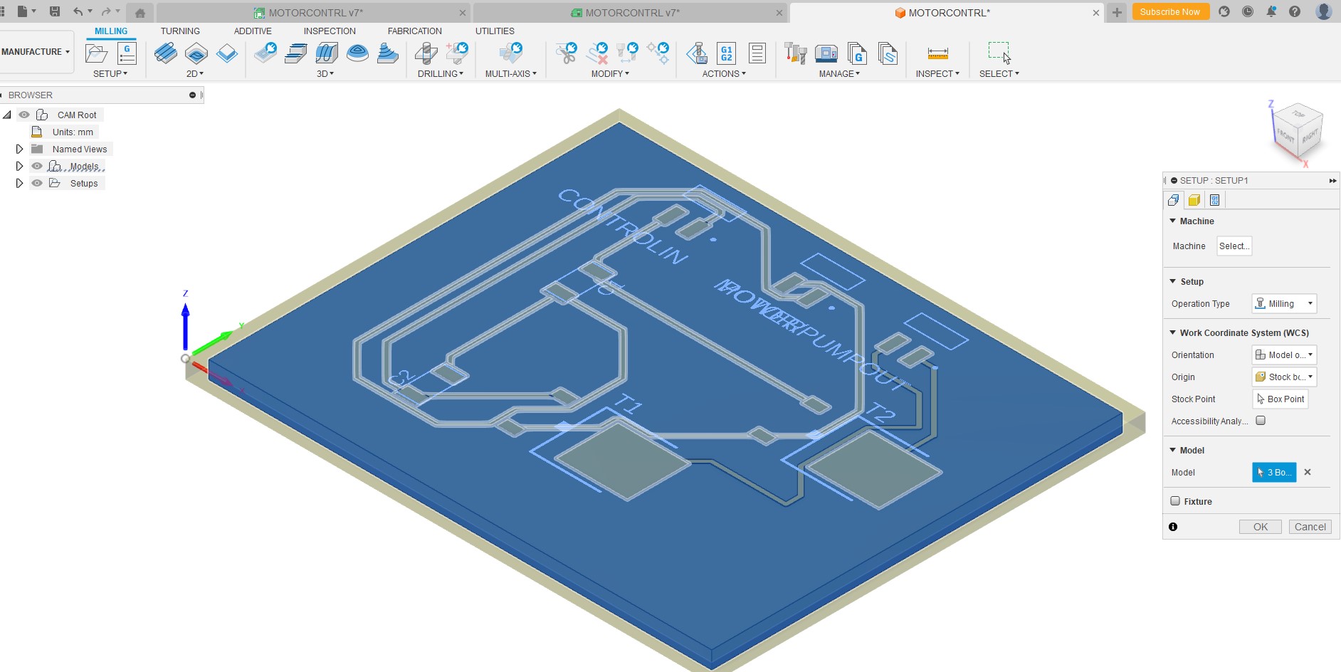
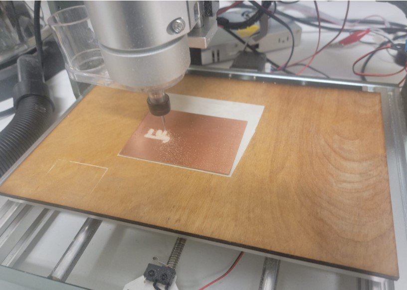
Motor control board milling
Now I was ready to mill. I used the same set up with my Genmitsu 3020-Pro-Max from last week here
The tool path looked good
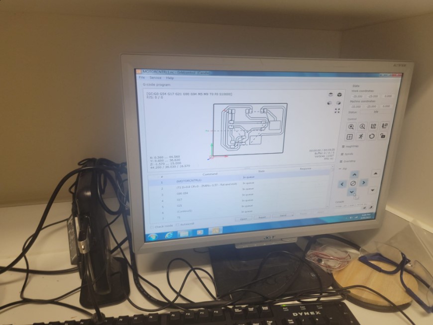
Got to cutting using a 0.8mm end mill
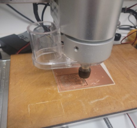
I deburred and washed the board
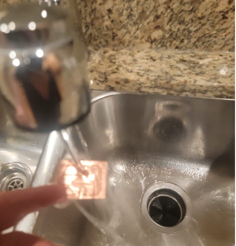
Now we are ready to stuff and solder
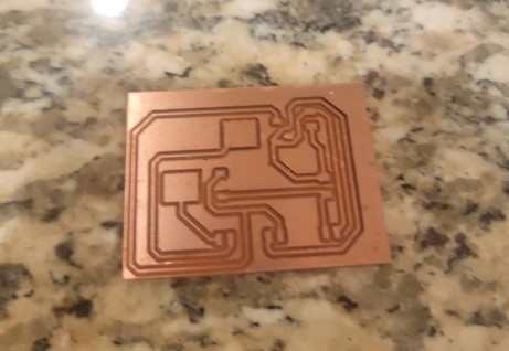
Here are all the components
And we are ready to test
After stripping the connectors on a number of boards and after rethinking the machine design I decided the break this board into 2 one for the motor and one for the pump.
I also increased the side of my traces to 30mil and replace the pad for my connector with A better connector from the fab library
I started testing the board and it seemed like now matter what I did the Sources and Drain of the transistor was always connected.
I checked for shorts, I added a pull down resistor to ensure the gate is 0 and not joy. The source and drain are connected.
I went back to the lab and got another 2 transisotr (the lab only had 3 of them) and they all seemed to do that same.
I reviewed them with my instructure and fellow student who is an electrical engineer and they could not find why it was acting this way other then it may be a bad batch of transistors. We put in an order for some more and for now this part of the project is on hold until the arrive.