Final Project
My project will be a vegetable washing machine
Research
What will it do?
Goal is to create a kitchen appliance that can wash and dry greens and other vegetables via a pre set cycle both saving time (and potentially water)
Who's done what beforehand?
So far I only found limited similar project within the fab academy community and a few outside.
Fab Academy projects
Outside of fab academy:
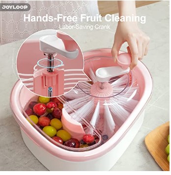
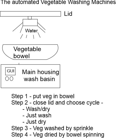
- I like the automated spinning salad dryer that the You Tuber The Practical Engineer designed
I think that he has a good spinner design and using this approach can allow me to allow users to put in any colander they wish.
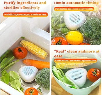
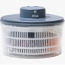
- Commercial solution are mainly ultrasonic, manual or focused on drying (salad spinners)
Here are some examples
What will you design? I will design all aspect of the project with 4 major components
-
The box / frame of the machine and water reservoir
-
The spinning mechanism
-
The machine lid and water dispensing mechanism
-
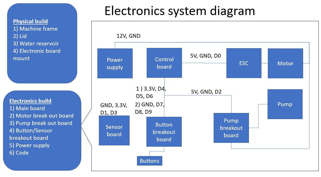
Control board electronics - main board, pump breakout board, motor breakout board, button breakout board
What materials and components will be used?
The main materials are
-
T Rails + Plexiglass
-
3D print filament - TPU, PLA and XTC3D finishing resin
-
Electronic components and PCB boards, motor/ESC and pump
-
Molding plastic / rubber
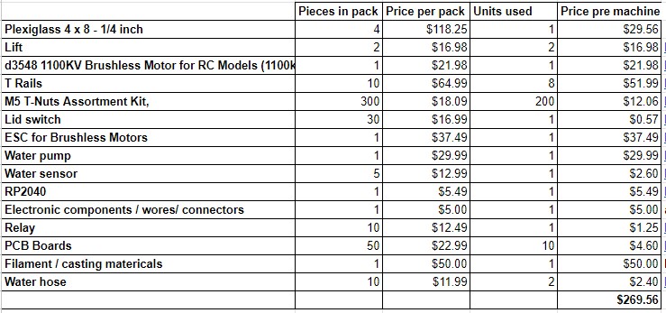
Below is a full BOM
Where will come from?
Most are either provided by lab, purchased from Digi key or Amazon
How much will they cost?
What parts and systems will be made?
Washbasin/box/frame, drain/skirt, spinning plate, lid, water reservoir, electronics boards.
Only things not made are: Motor + ESC, pump, salad spinner bowl, water tube, sprinkler head, power supply
What processes will be used?
- 3D print
- Laser cutting
- PCB Board milling
- Molding and casting / resin
- System integration
What questions need to be answered?
- Spinning mechanism - chain/band vs. direct drive (already answered)
- Frame materials - (already answered - TRail )
- Water drainage approach - TPU printed sloped base
How will it be evaluated?
- does it wash and clean greens / veggies
Project description
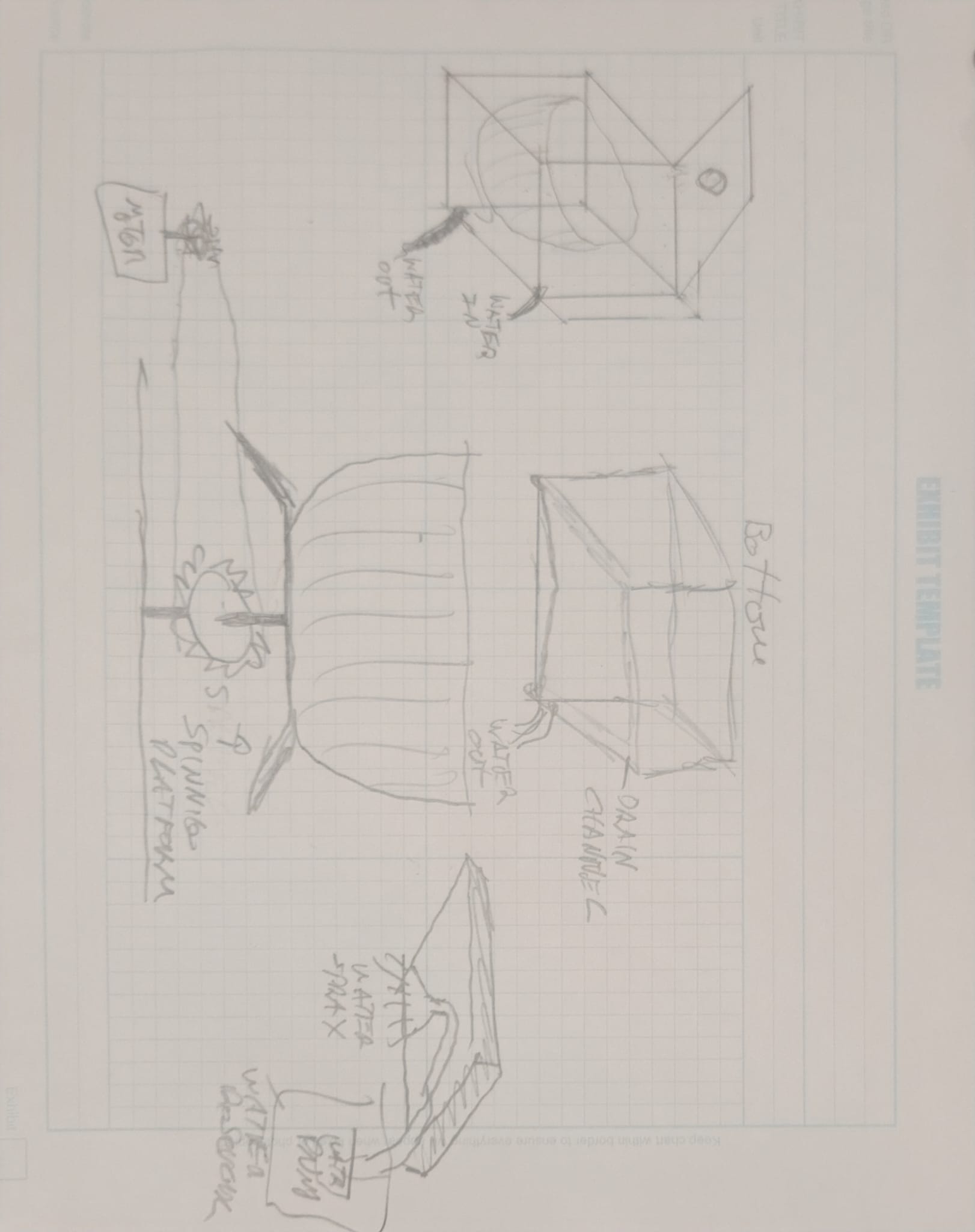
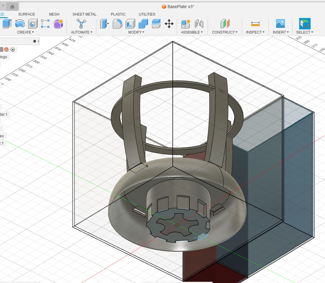
Here is a first cut at the base:
There are 4 main parts to the appliance
-
Water reservoir
-
Main container (Wash basin)- base is designed to have a gravity fed drain
-
Lid with build in sprinkler
-
Vegetable holding bowel that sites in the Wash basin and spins to dry
There are 2 Motor/pump used
-
Water pump to move water from reservoir to sprinkler head
-
Motor to spin Vegetable bowel
There are 2 potential sensors
-
Lid sensor - stop operation if lid is open mid cycle
-
Water level sensor to alert if reservoir is empty
Microcontroller usage
-
Control sequencing of pumps / motors
-
Interrupt operation if sensor is triggered
-
Manage GUI
GUI
- Button that allow user to start cycle
-
Wash only
-
Dry only
-
Wash/dry
- Announce alerts (ready/water empty/finished)
Here is a another view of the merging design
Project: Align parts to Fab Academy weekly topics
| Weekly topics | Parts |
|---|---|
| Computer controlled cutting | Outbox / wash basin holder |
| Electronics production | Controller, motor ESC, Sensors |
| 3D Scanning and printing | Motor housing, water connectors, sprinkler head, sproket/chain for motor drive |
| Electronics design | sensors / controller board / Motor ESC |
| Computer controlled machining | Controller board |
| Embedded programming | Cycle design / User input |
| Molding and casting | Drain / Spinning plate |
| Input devices | GUI buttons / Sensors |
| Output devices | Screen |
Key component breakdown
Outer box - Plexiglass
Wash basin holder - Plexiglass / 3d print
Water reservoir - molding / buying
Electronic housing - 3D print
spinner mechanism - 3D print
Bowel - Molding / casting
Lid - 3D Print
Water pump / sprinkler mechanism - 3D print / electronics
Sensors - 1) Lid sensor 2) Water level sensor
Controller board -
Display/Buttons
Water connections - 3 Print or buy
Project: Build / system overview
My build split into the physical build and the electronics
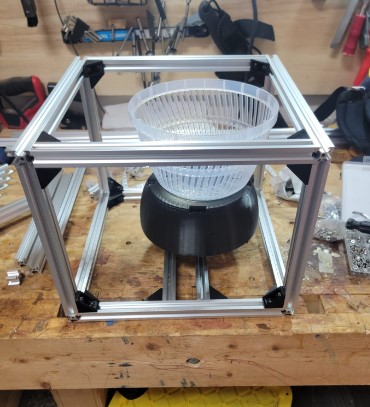
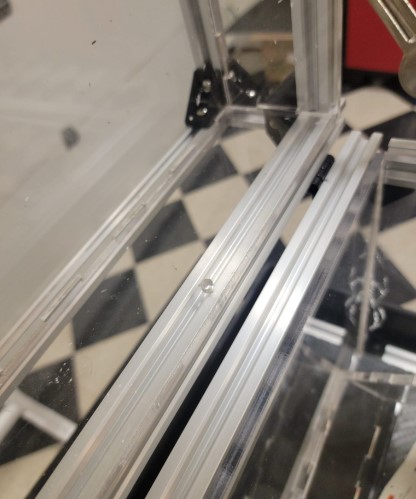
Box: Frame build
I decided to use a similar method that we used in machine week of T rails for the outside frame and then 1/4 inch plexiglass for the water tight box and water reservoir that are both mounted in side the frame
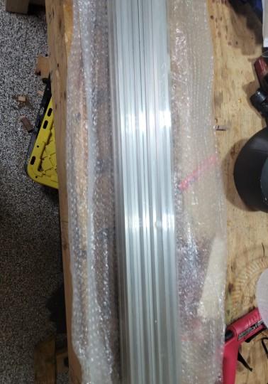
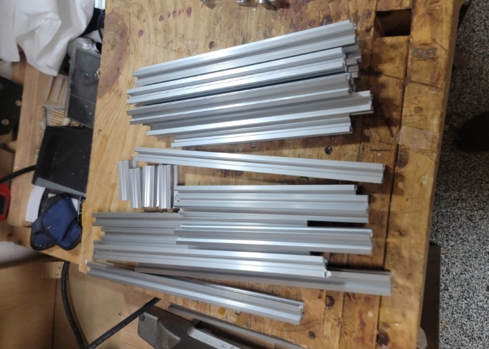
Using a chop saw and aluminum cutting blade I got all the pieces ready for assembly
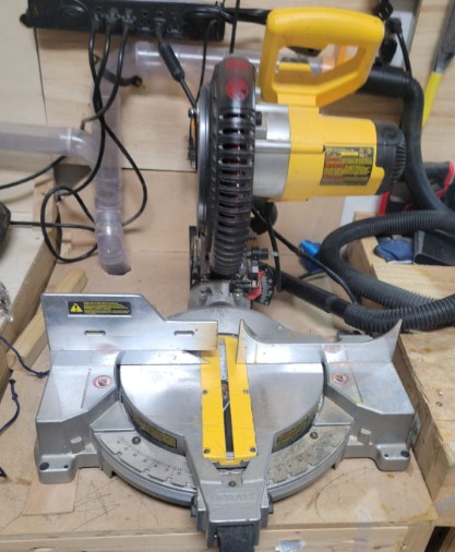
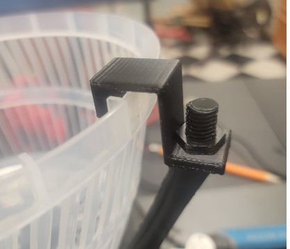
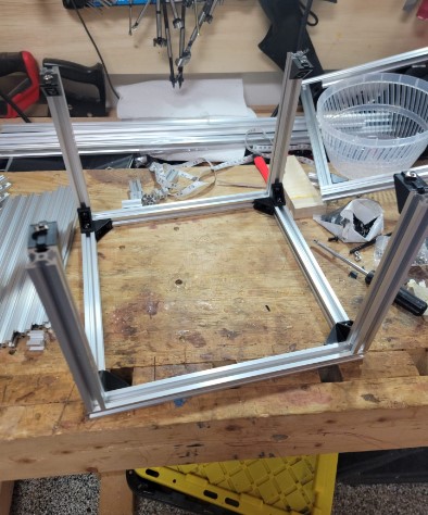
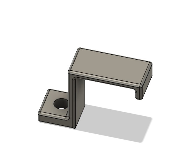
3D printed bracket will be key together with T Rail M5 screws and bolts
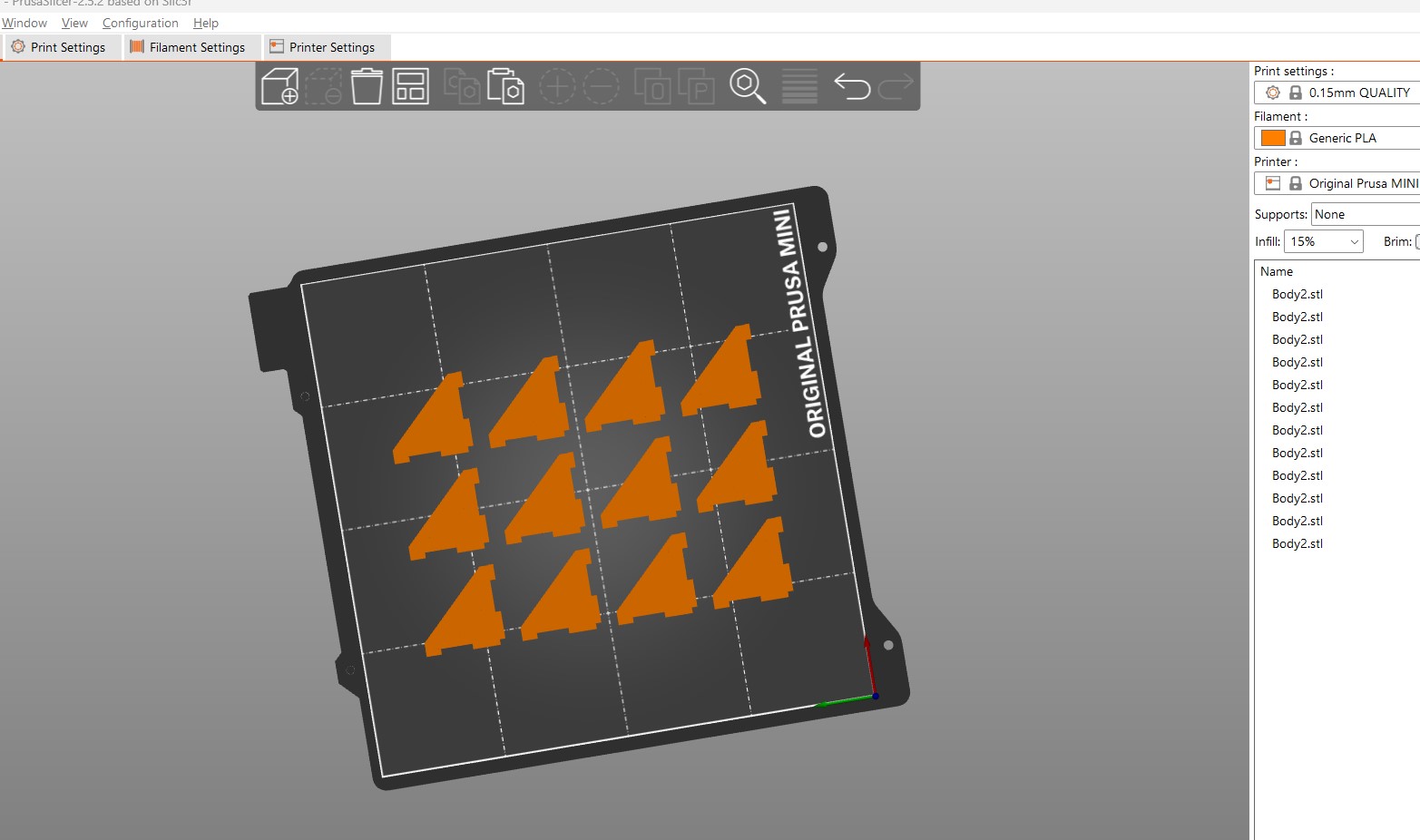
You can see the bracket in action
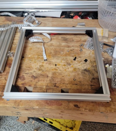
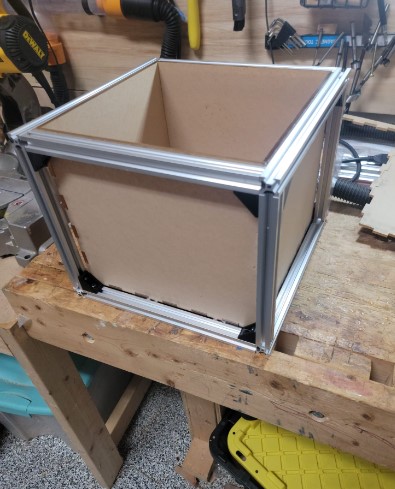
Assembly of the box was straight forward
COnfirming the size with spinning plate and bowel
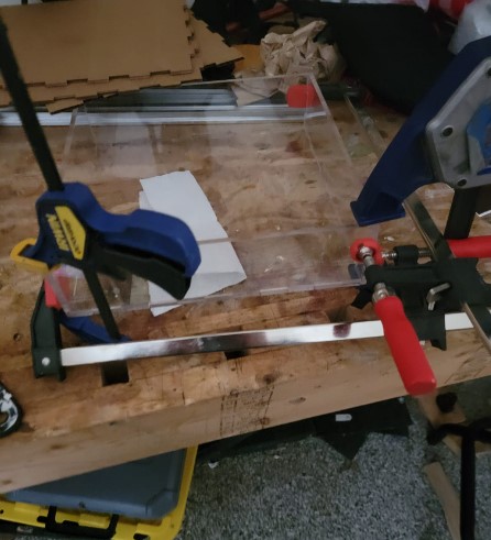
To make the water proof interior box I decided to use 1/4 plexiglass that I will laser cut and then use cement and possible silicon to water proof
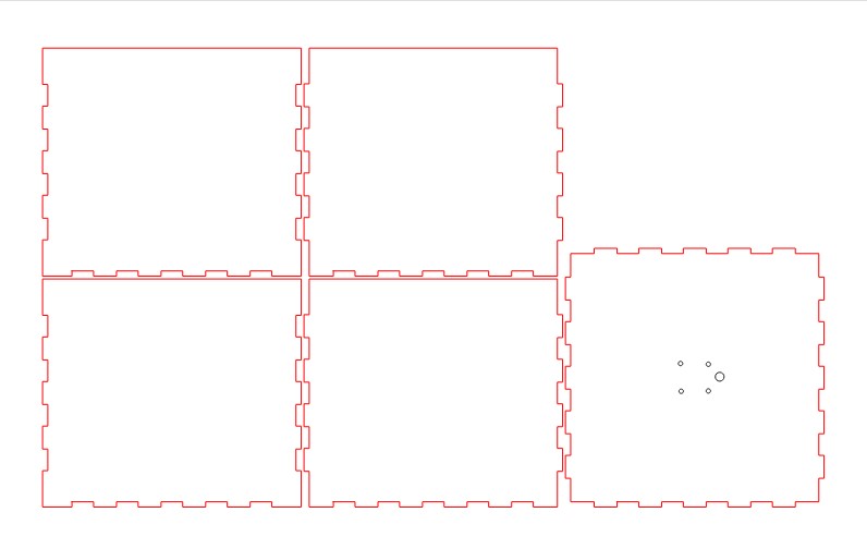
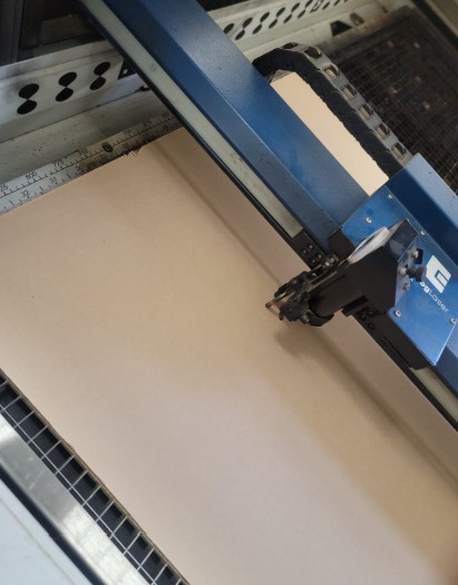
I used the big epilog laser at the fab lab. Setting for 1/4 inch plexi glass was 100% power and 10% speed.
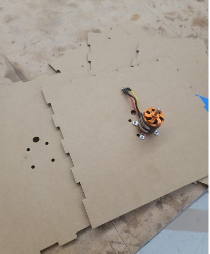
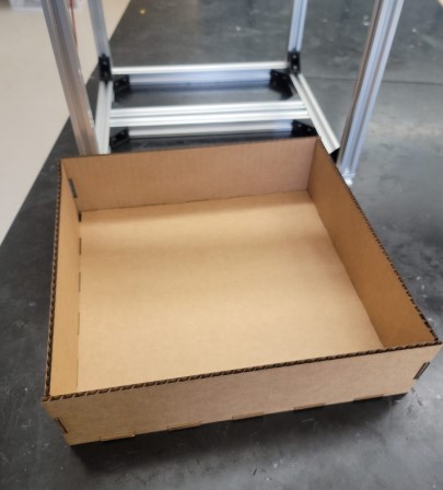
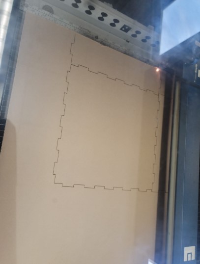
I first cut and assembled a cardboard set to make sure it all worked well as I only have 1 sheet of plexiglass. I made sure the mounting holes for the motor were positioned correctly
Now it was time to cut the plexiglass
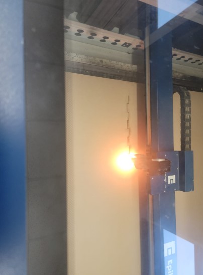
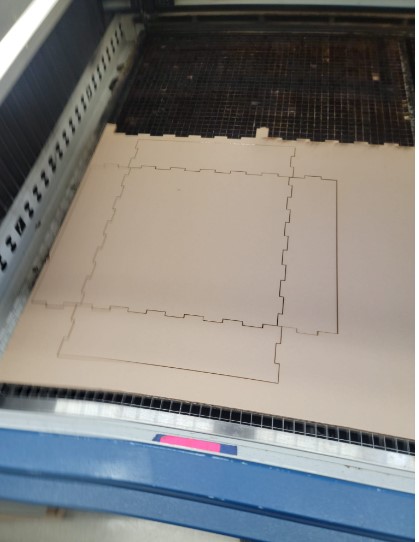
4 of the five panels cut fine on the left side but the right side of the laser did not cut through. I refocused the laser on the right side and ran the cut for the 5th panel with 3 passes. Discussing with the person in charge of maintaining the laser it seems like they were having a focus issue they were working through.
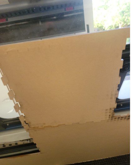
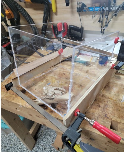
Once they were all cut the box fit nicely into the frame
Now I needed to glue it together and so I used a plexiglass cement with the following data sheet
I only did used it in the garage with the car door open to ensure enough ventilation
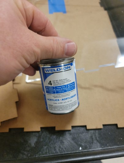
This applicator was very useful
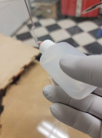
I used clamps to keep it together until the cement dried
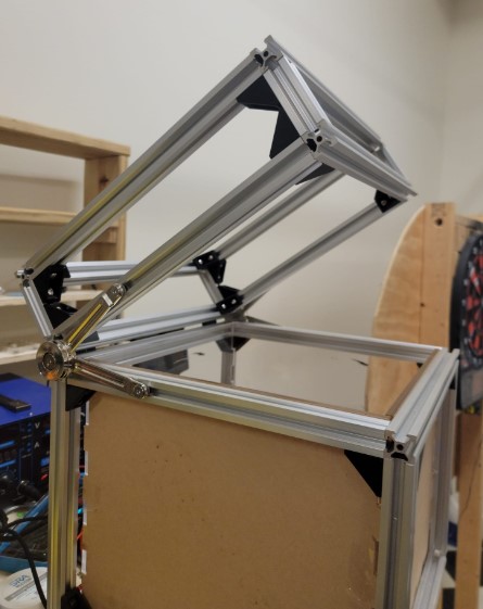
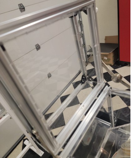
Box: Lid
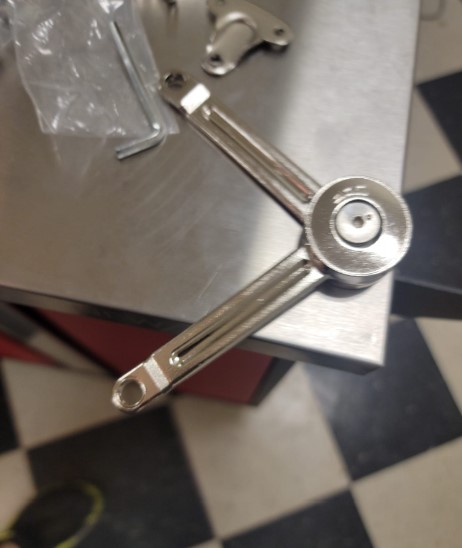
The lid assemble was a smaller version of the box assembly with an addition of a hinge and a Door Lift Stay Support Hinge Damper
They were both easy to mount onto the TRails
You can see the lid stay open
Now it is time to fabricate the internal plexiglass box
First I cut out the shape from cardboard to make sure it would fit
Looks good
Now cut the plexiglass
Clean cut
Use the clamps and cement.
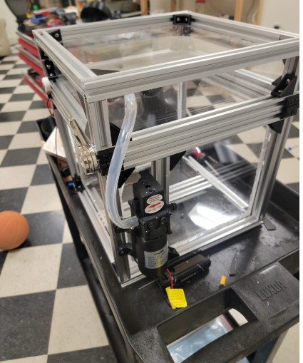
I added holes to allow it to be secured to the T Rail
Here you can see the water pump mounted and another hole for the water tube to go into the lid
Box: Water reservoir
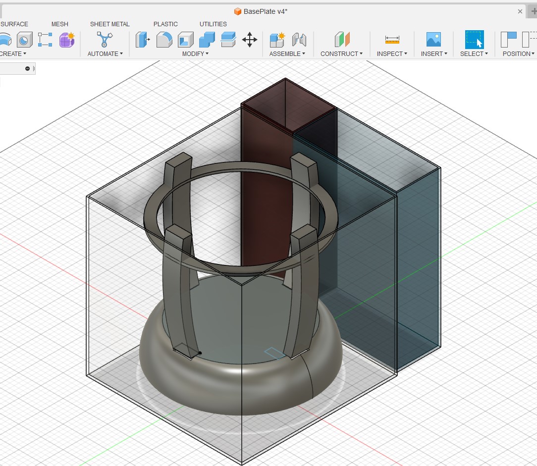
Box: Spinning plate
First I set up some user parameters I will use in sizing the spinning plate and it base

Now I made a round leg for the plate to sit on

To create the shape of the base I will create a new sketch on the top of the base leg. I then create a circle and replicate it using the circular pattern tool followed but a cut.


I then sketched on top again and created a circle to create the plate itself

Here I made a mistake as I did not select the whole plate and where the handy timeline tool come into play

And we are back on track. I wanted to create a downward facing lip in order to provide some water protection for the spinning mechanism during the dry cycle.
To do this I am going to draw a sketch of the lip and have it rotate around the plate center axis
Start with sketch

Then used the revolve to create the lip and set it to join the plate base.

and there you go a first cut at the base plate

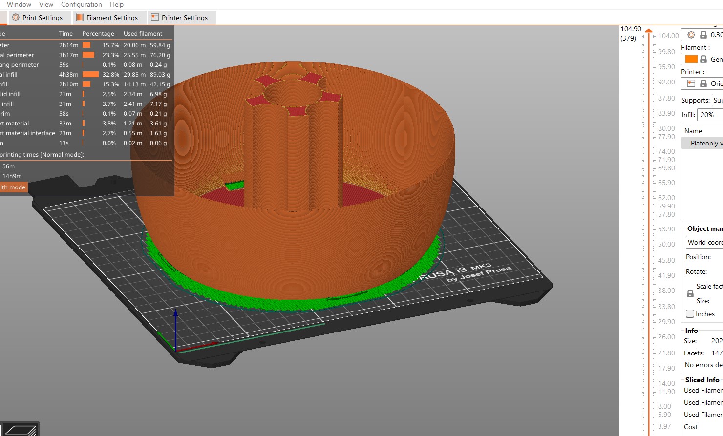
Box: 3D printing the plate
I started off by printing a test model aprox 50 of the size
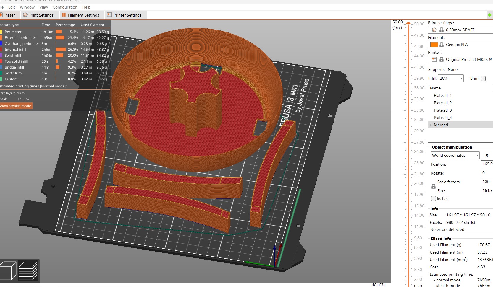
After 5 hours, here it is:
When I put it up to the salad spinner bowel I have it seemed to me that the overall size of the machine
can be much smaller then I originaly planned.
I think a good approach is the max the size of the plate I can print on the MK3S
The original size had a 320mm diameter but I am going to resize it to a 200mm diameter
I used the scale command leaving the Z as is and scaling the X and Y to 62.5% of the original
Here it is printed
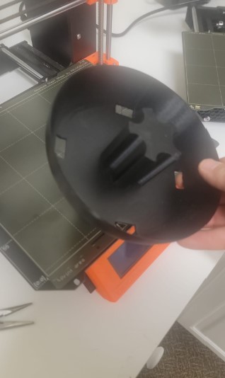
Now that I liked that size in order to make every thing work in fusion I had to go back and resize the plate in fusion to match.


Now we are ready to create the bowel holders
Box: Out runner motor mounting
See below for discussion on the motor drive selection and decision to move to a direct drive mount on a outrunner motor. I am used a D3548.
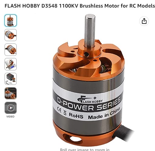
I found a model of the motor I am planning to use on GrabCad

This an out runner and I would like to cut its shape into the bottom of the spinner to test a direct drive
As the CAD was made of many many pieces it was easier to create a similar shaped body. I traced the profile and used the revolved function to create an new body
s


Now I used the combined command to cut this out of the base of the plate for a direct mount

Creating a nice mount for the plate - i also think i do not need the spinner base any more.

I knew there was going to be a lot of stress on this when the plate spins so I filet everything I could to strength the joints.

Got it ready to 3D print
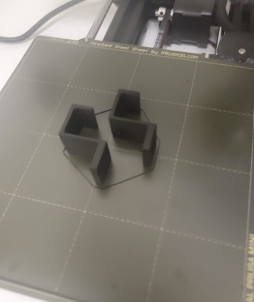
Box: Bowel holder
Initially I printed a basic arm to get a physical sense of the shape and size
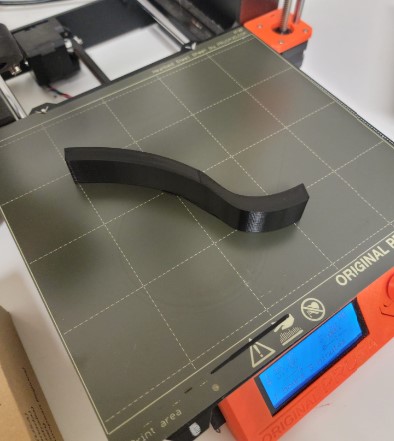
After have a basic shape in the early design I needed to have a pieces that was help in place on the plate.
I started by adding a wedge at the plate level and tweaking the shape but it was very unstable
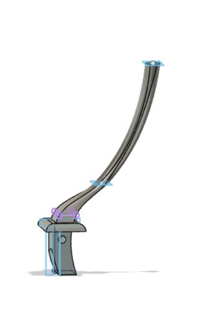
I decided to use to features to do that.
- Redesign the base to snugly fit on the shape of the plate
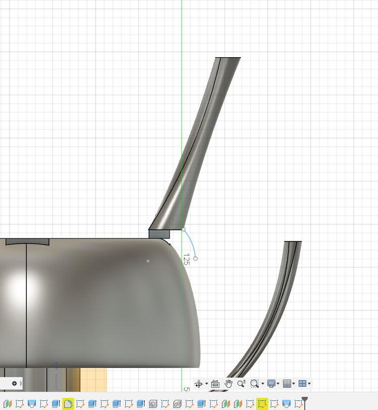
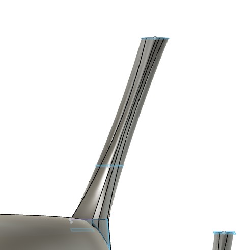
- Create a threaded rod on the bottom and print a nut that will hold the are in place
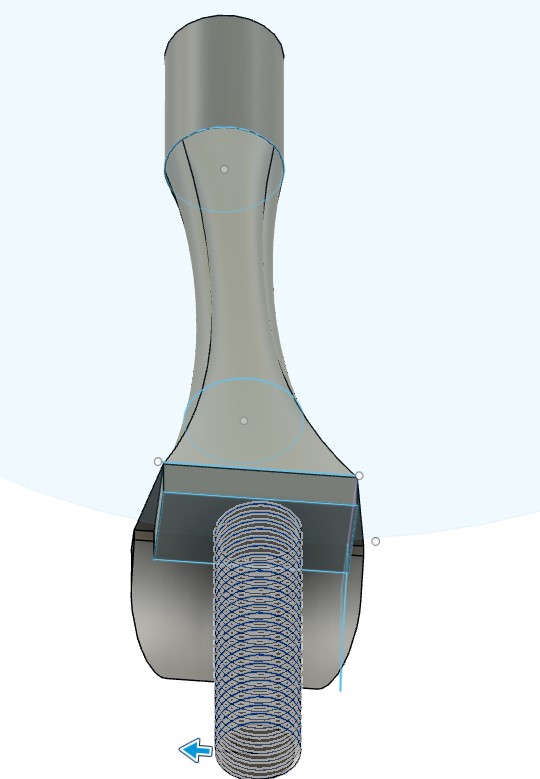

Here is it assembled
and now to test
When discussing my progress with my local instructure Dr. Fagan, the feedback I got is the need to have a screw to hold the plate to the motor shaft


I decided to put in a pocket to hold the bolt

Then a screw hole all the way to motor shaft

Once the design looked goo it is time to reprint the plate.
After 13 hours we have a new plate

And the screw fit with the bolt holding it in place.

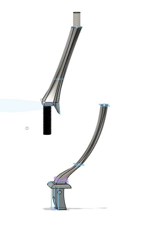
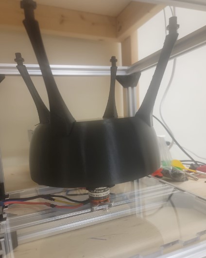
Box: Bowel hooks
To ensure the spinner bowel does not fly out I need to add a hooks that will connect to the top of the plate arms and hols the bowel in place
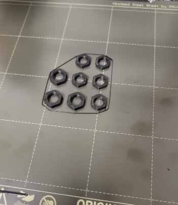
I decided to go with a simple 3D printed design
Got them 3D printed
And istalled