-
Mitalee Parikh authoredMitalee Parikh authored

#Computer controlled machining
This week is about making something big using a CNC milling/routing machine. I want to explore the possibilities of CNC machining - drill, pocket, dog-bones, nesting, etc. I tried to make a versatile furniture piece so that I can use different joints and experiment with them.
Page Summary
- Introduction
- Design
- Nesting
- CAM
- Test settings
- Machining
- Assembly
- References
- Design Files
- Introduction
Material available for use is a veneer plywood of size 2440 x 1220 x 17 mm.
On checking with a vernier caliper, thickness varies between 16.9mm and 17.1mm. So I'll use an average of 17mm thickness for my design.
I wanted to make a desk with adjustable height so after some viewing some references, I decided to make trestle legs for a desk setup.
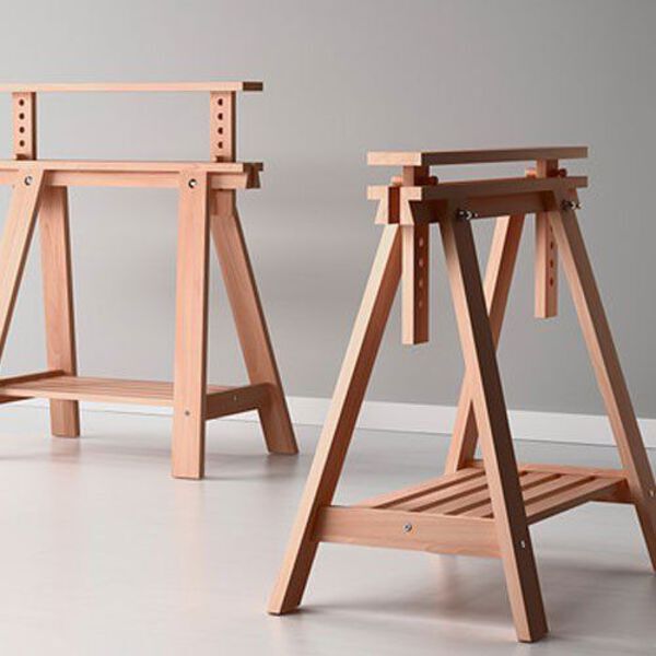
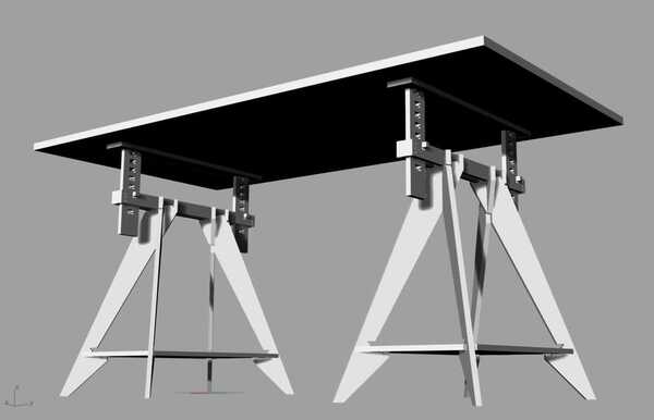
I started by making a 3D version of IKEA's FINVVARD to understand how it works.
Since, I didn't have access to the lab during this week, I did the CAM part according to tools used in FabLabBCN.
Later when I used FabLab SP, I did it again using Vcarve Pro.
- Design
I learnt about some details from the 50 Digital Joints poster. For the group assignment, I made a joint using both profiling and pocketing.

I also made some versions of the finger tennons, lapped finger tennons, throughhole finger tennons to design the trestle.


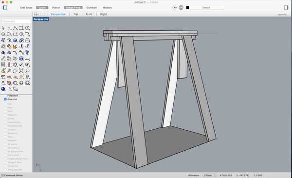
Here is how the final legs look. I need to make 2 of these and put any flat board on top to make a tabletop.
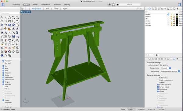
Here it is in 3D.
- Nesting
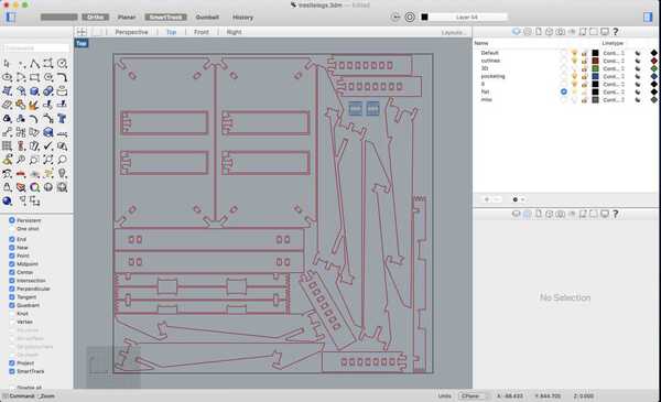
Next, I lay everything flat on the XY plane and did a make 2D. For nesting I used an online service called nestandcut.com to nest all parts in twice the quantity on a sheet of 1220x1220x15 mm. (Half a sheet). I uploaded a dxf file that I export from Rhino and imported the nested dxf back.
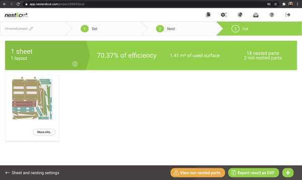
I made some changes manually to fit it all in the available sheet. Like I put two parts insode the big board and nest it within to make more space for the missing parts. Here is what that looks like:
- CAM
RhinoCAM
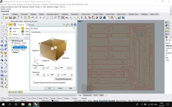
Next, I shifted to the Windows partition of my computer and installed RhinoCAM. I opened the RhinoCAM machining browser plug-in in Rhino6. First I set it to MILL. In the program tab, I set up the material stock - 1220x1220x15.5 mm, the machine details - 3 axis , post - shopbot.
I set the origin at the left bottom corner and the Z at the top of the material stock.