-
Mitalee Parikh authoredMitalee Parikh authored

#Input Devices
This week, I used an Arduino board to read an analog temperature sensor.
When I have access to a lab, I will make a microcontroller board with a colour sensor as input.
###Page Summary 0. Inputs using Arduino board (no lab access)
- Probing an input device's analog levels and digital signals
- Designing a micro-controller board to read input
- Milling
- Stuffing and testing
- Programming
- Reading the input
- Design Files
- Important and Interesting Links
- Inputs using Arduino board (no lab access)
I wanted to start with a simple project to get the basics right and understand fundamentals of using inputs with microcontroller board. Using an Arduino Uno board with it's documentation was very basic. So I did this befordesigning my own board.
For reference, I used the Arduino Project 3 ait used the temperature sensor.
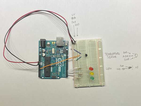
I started by collecting all the components.

I used this schematic to connect everything.
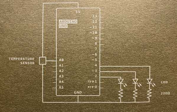
The circuit setup was fairly easy. This is how it looks.
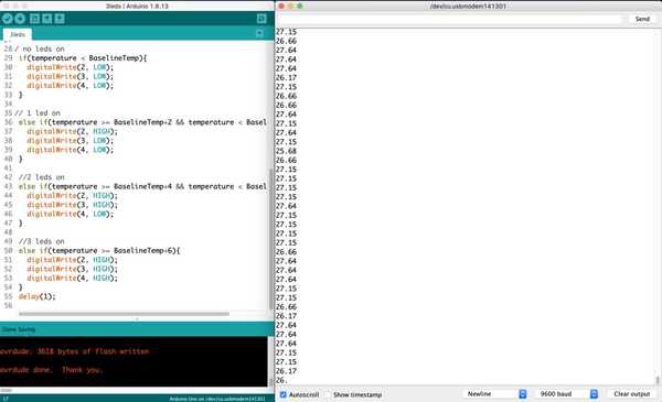
At first, all lights were continuously on. I checked the serial monitor and saw that the temperature was around 2degrees without touching. So I adjusted the baseline temperature to 25 in the sketch. After some trial and error, adjusted the sketch so that on touching it lightly for about 5 seconds, the second led lit up and on holding it tighfor some seconds the third led lit up. The serial monitor indicated temperature range from 26-32 degrees.
So an increment of 2-4-6 degrees worked out perfectly.
This is it in action:
The code was fairly simple as well. You can find it here - Sketch
Understanding the basics:
```
// defining constants
const int SensorPin = A1; // analog template input from temp sensor
const float BaselineTemp = 25.0; // reference temp defined
      // serial port on and setup runs once
      void setup(){
        Serial.begin(9600);                                        // serial monitor baud rate
        for(int pinNumber = 2; pinNumber<5; pinNumber++){          // for all pins 2, 3 and 4 connected to leds
          pinMode(pinNumber,OUTPUT);                               // define them as output
          digitalWrite(pinNumber, LOW);                            // leds off by default
        }
      }

      // loop - read sensor input
      void loop(){
        int sensorVal = analogRead(SensorPin);                      // read analog value from temp sensor

      // serial monitor output - temperature
        float voltage = (sensorVal/1024.0) * 5.0;                   // calculate voltage from temp sensor value
        float temperature = (voltage - .5) * 100;                   // calculate temperature from voltage
        Serial.println(temperature);                                // print temperatue on serial monitor


      // no leds on
        if(temperature < BaselineTemp){                             // defining relation between input temp and reference
          digitalWrite(2, LOW);
          digitalWrite(3, LOW);
          digitalWrite(4, LOW);
        }

       // 1 led on
        else if(temperature >= BaselineTemp+2 && temperature < BaselineTemp+4){
          digitalWrite(2, HIGH);
          digitalWrite(3, LOW);
          digitalWrite(4, LOW);
        }

        // 2 leds on
        else if(temperature >= BaselineTemp+4 && temperature < BaselineTemp+6){
          digitalWrite(2, HIGH);
          digitalWrite(3, HIGH);
          digitalWrite(4, LOW);
        }

        // 3 leds on
        else if(temperature >= BaselineTemp+6){
          digitalWrite(2, HIGH);
          digitalWrite(3, HIGH);
          digitalWrite(4, HIGH);
        }
        delay(1);                                                    // delay 1/100 sec before starting loop again
      }
```- Probing an input device's analog levels and digital signals
- Designing a micro-controller board to read input
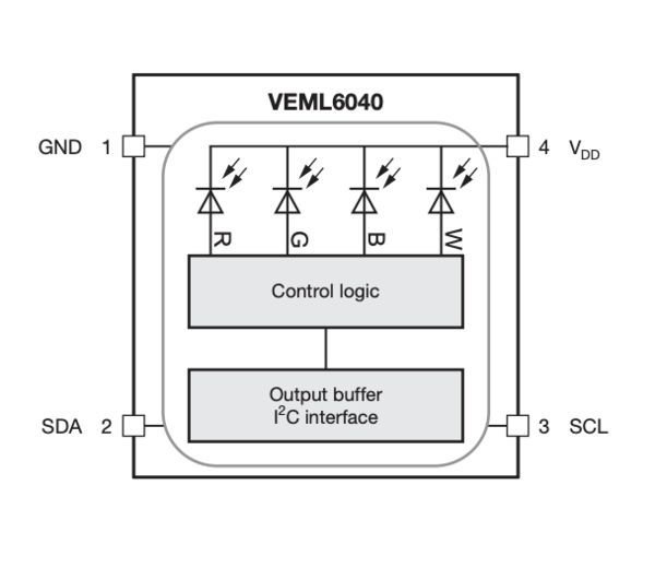
For this I want to try measuring light color using a RGB colour sensor.
First task is to select a microcontroller for the selected sensor. By looking at the datasheet and pinout of the sensor VEML6040, it needs only SDA and SCL to be connected by I2C communication protocol. The SDA needs a pull-up resistor.
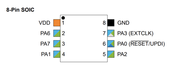
The microcontroller itself needs to Tx, RX to be able to connect through UPDI to a programmer.
I choose the Attiny412 because... ATtiny412 Datasheet VEML6040 - RGBW Color Sensor with I2C Interface
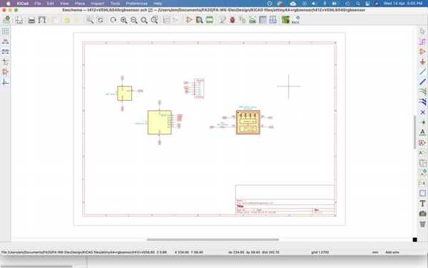
Downloaded the footprint from Here
Installed the symbol and footprint on KiCAD using this guide


- Milling
- Stuffing and testing
- Programming
- Reading the input
- Design Files


Schematic pdf
Schematic file
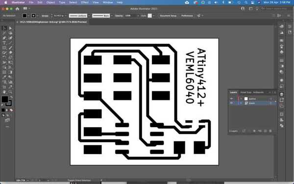
traces
Kicad pcbnew
- Important and Interesting Links