-
Mitalee Parikh authoredMitalee Parikh authored

Computer controlled machining
This week is about making something big using a CNC milling/routing machine. I want to explore the possibilities of CNC machining - drill, pocket, dogbones, nesting, etc. So I want to make a big jigsaw puzzle with different kinds of digital 2D joints.
Measure material
Material available for use is a veneer plywood of size 1220 x 1220 x 15 mm.
I will check exact thickness with a vernier caliper when in the lab.
Design
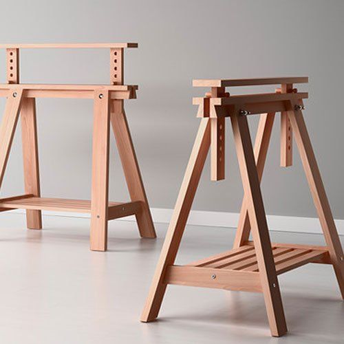
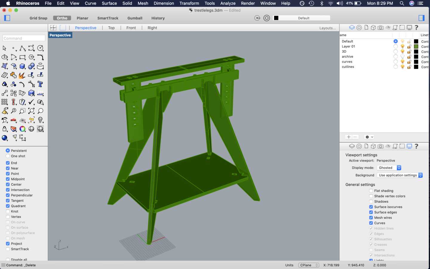
I wanted to make a table with adjustable height so after some viewing some references, I decided to make trestle legs for a desk steup. I started by making a 3D version of IKEA's FINVVARD to understand how it works.
Then I started making individual joints so they can be digitally machined in 2-axes or 2.5-axes. I used some details from the 50 digital joints poster to design some details.

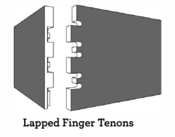
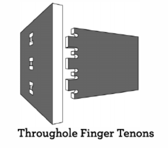
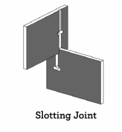
I made some slotted joints, and versions of the finger tennons, lapped finger tennons, throughhole finger tennons to design the trestle. 


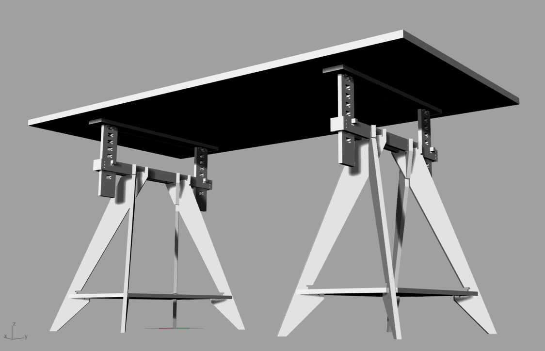
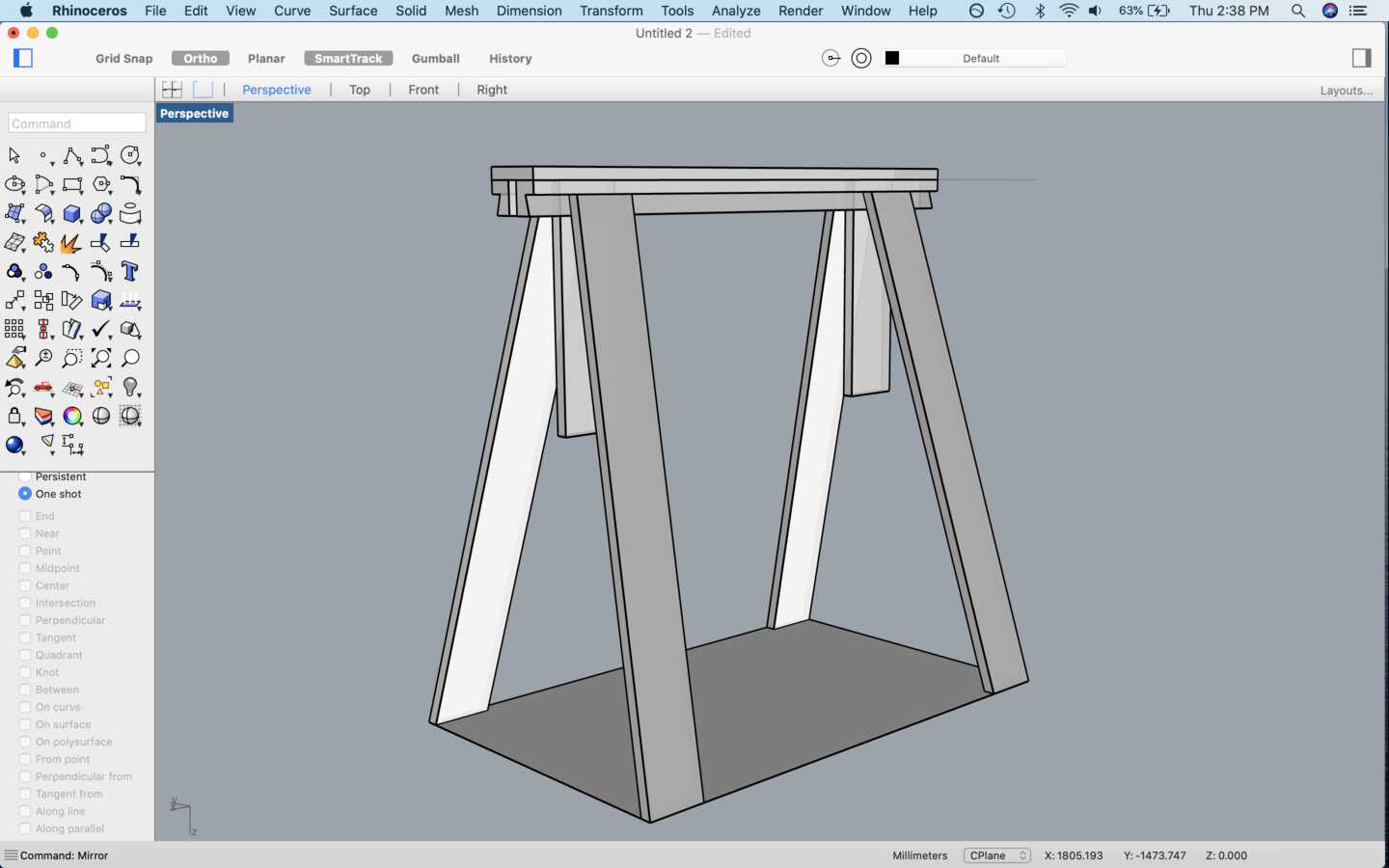
Here is how the final legs look. I need to make 2 of these and put any flat board on top to make a tabletop.
Cutting file + Nesting
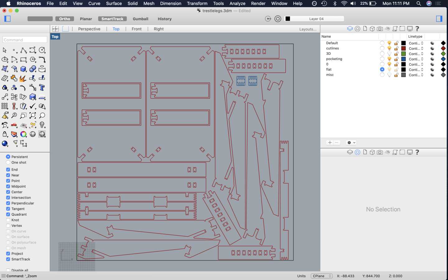
Next, I lay everything flat on the XY plane and did a make 2D. For nesting I used an online service called nestandcut.com to nest all parts in twice the quantity on a sheet of 1220x1220x15 mm. (Half a sheet). I uploaded a dxf file that I export from Rhino and imported the nested dxf back.
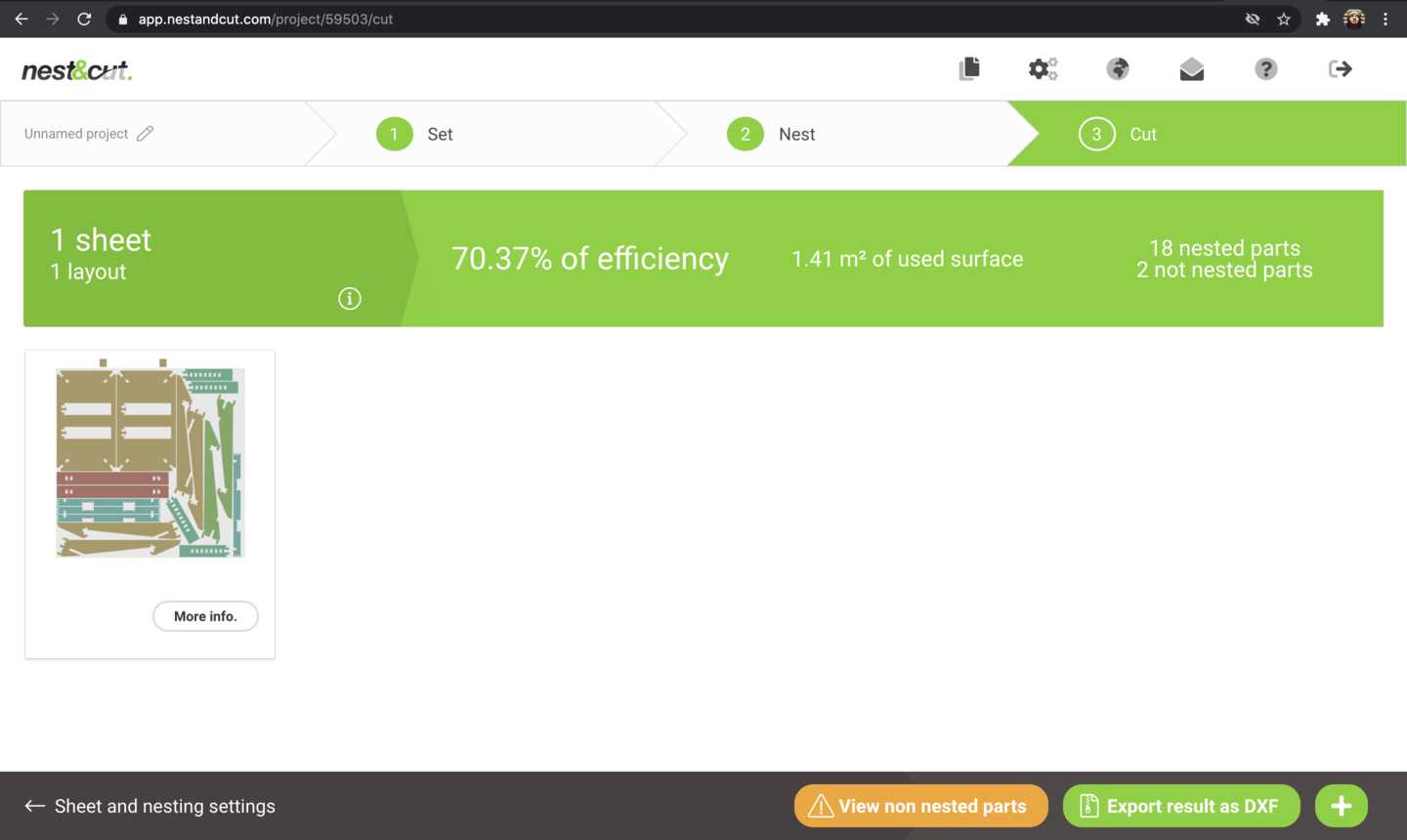
I made some changes manually to fit it all in the available sheet. Like I put two parts insode the big board and nest it within to make more space for the missing parts. Here is what that looks like:
CAM
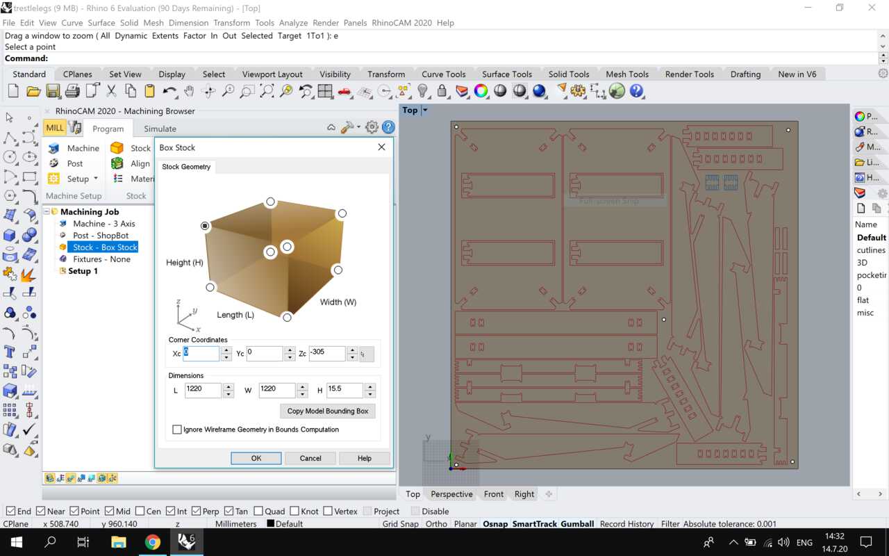
Next, I shifted to the Windows partition of my computer and installed RhinoCAM. I opened the RhinoCAM machining browser plug-in in Rhino6. First I set it to MILL. In the program tab, I set up the material stock - 1220x1220x15.5 mm, the machine details - 3 axis , post - shopbot.
I set the origin at the left bottom corner and the Z at the top of the material stock.
Next I set the tool - Flatmill 6mm, refering to the class notes and some previous documentations:
-
Saved the tool as Flatmill 6mm
-
Holder dia = 50
-
Holder length = 45
-
Shank dia = 6mm
-
Tool dia = 6mm
-
Shoulder length = 30mm
-
Flute length = 30mm
Feed and speeds:
-
Speeds: 12000 rpm
-
Plunge: 2000 rpm
-
Approach: 2000 rpm
-
Engage: 2000 rpm
-
Cut: 2000 rpm
-
Retract: 2000 rpm
-
Departure: 2000 rpm
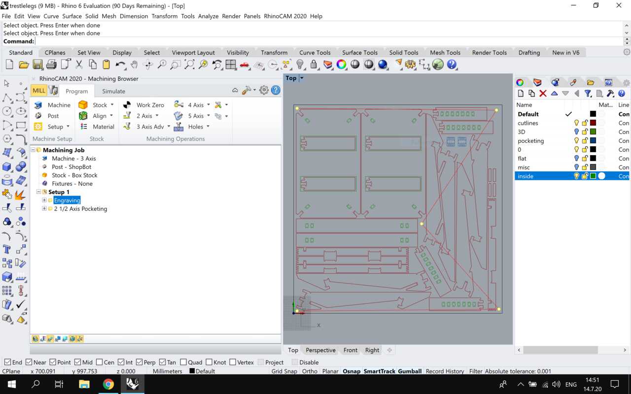
Next, in 2-axis functions there is a list of actions ypu can perform. For my design I needed engraving, profiling and pocketing.
Engraving
I set 5 points in the rhino file to engrave markings for screws to be drilled with a hand drill in the correct places.

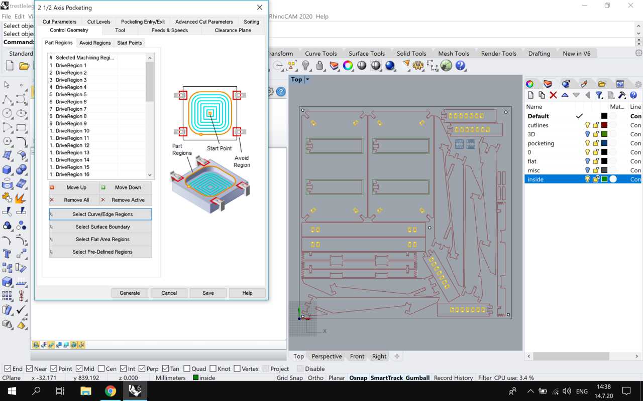
Pocketing
The insides of some parts that needed to be cleared were cut first. 2 parts needed pocketing at different heights, So after making adjustments in 2 different layers I changed the cut depth for both. 15mm for all parts except 2 where it was 10mm.
Settings
-
Cut pattern: Offset
-
Cut direction: Conventional (Up cut) - standard for plywood
-
Start point: inside
-
Rough depth: 12
-
Finish depth: 3
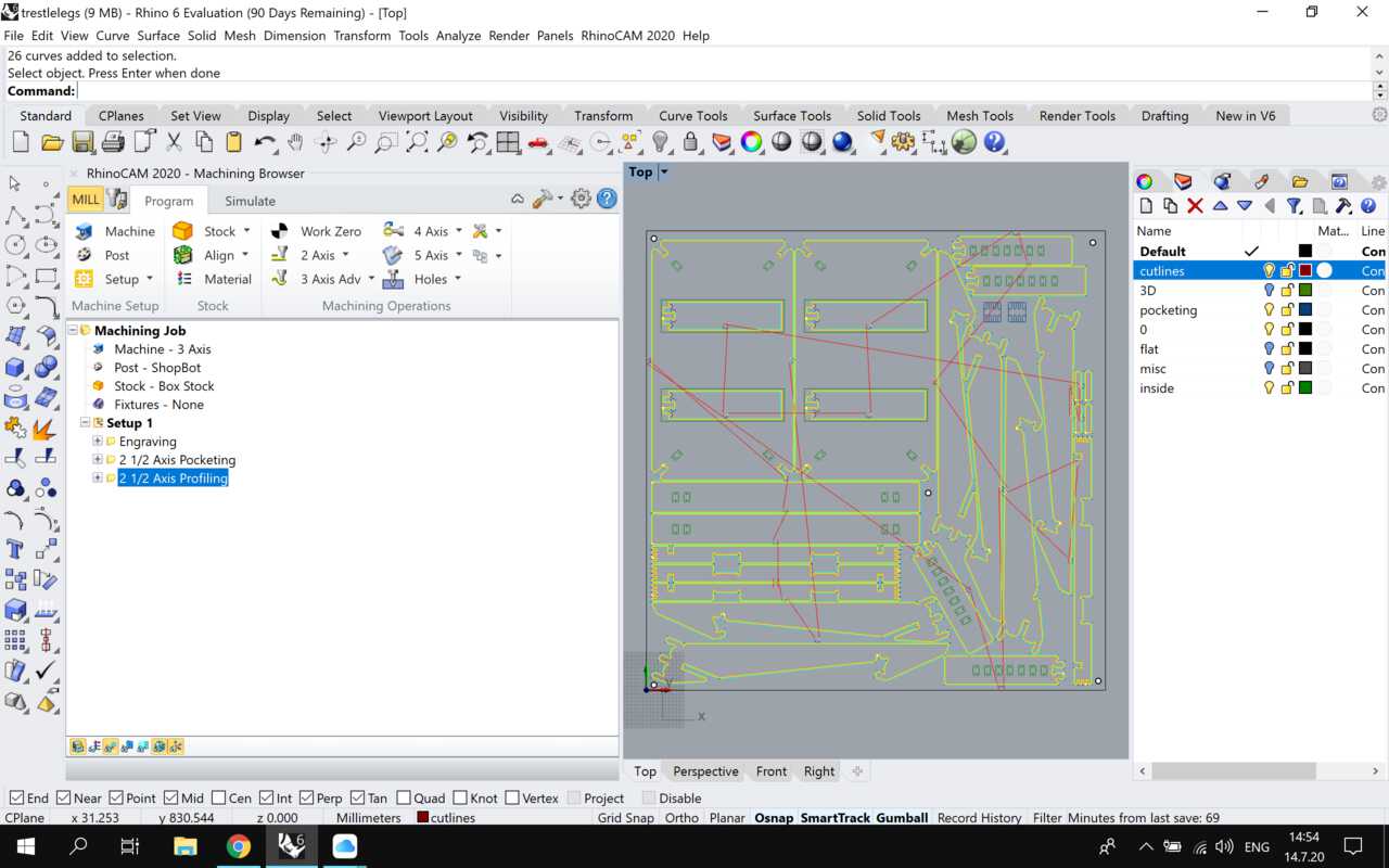
Profiling
To cut the outside profiles of the parts, I set the profiling for 2.5 axis. I also made another profiling - inside for 2 curves that needed to be cut on the inside.
Settings same as pocketing, set toolpath OUTSIDE the curves
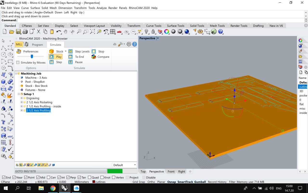
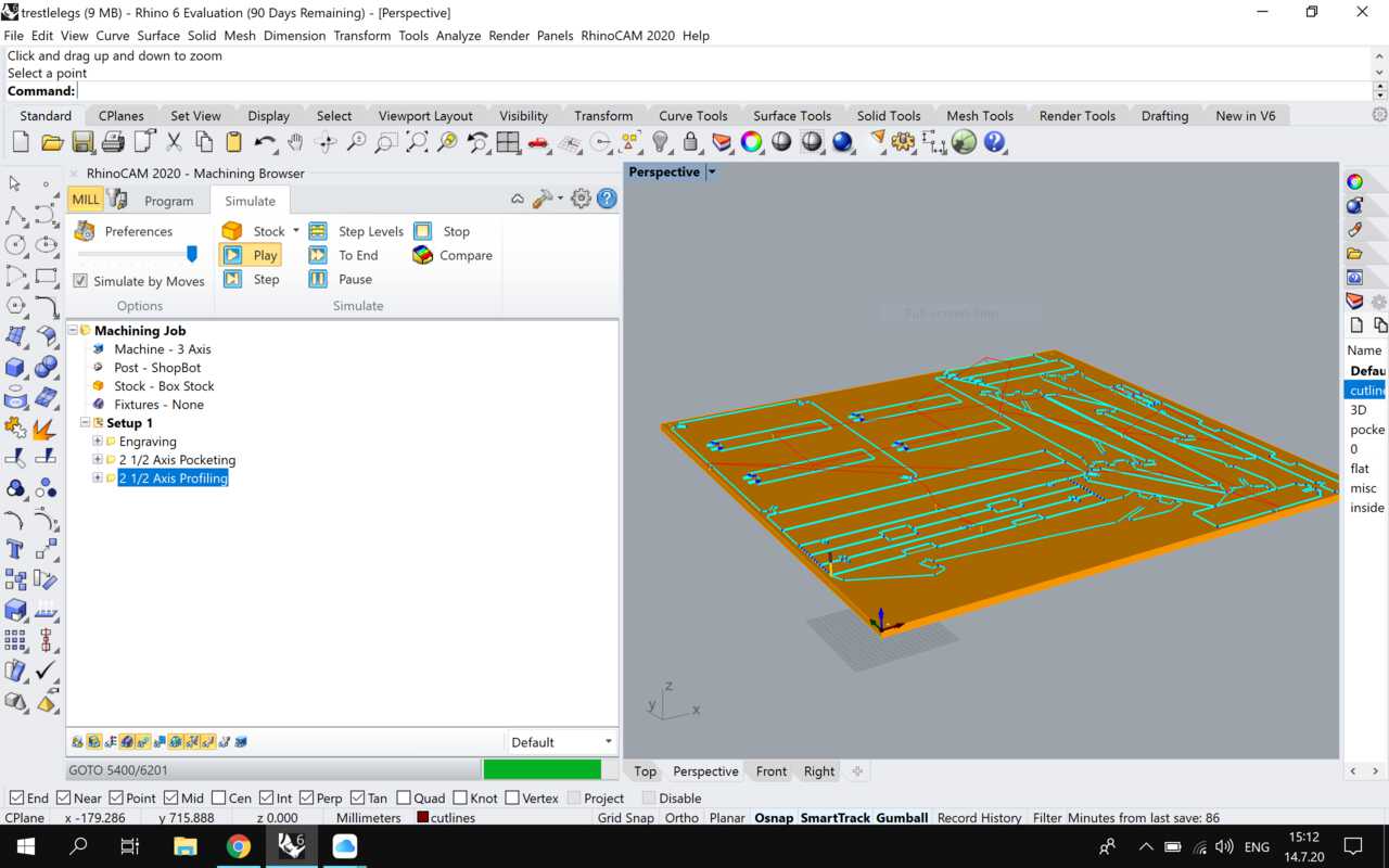
Simulation
Then I ran a simulation and found some errors in the settings.
- The cutting height did not match the level of the stock. It was cutting in the air. I adjusted this by going back to the material panel and changing the stock thickness to 15mm. (It was 300 by mistake)
- The tool path just ran once over all profiles and went in 15mm in one pass. I changed this by making the cut depth 15mm in roughing and finishing at 12 and 3 respectively.
- Some parts were creating double paths - so I deselected them from one layer and generated toolpaths again.
After running another simulation, it seemed fine.
Machining
Will do this part when I return to the lab.
Assembly
Will do this part when I return to the lab.
Here's how it should look when done. (w/o the top surface)
References
-
Design Files
-
RhinoCAM (Got an error while saving this - not all CAM changes can be saved, so not sure if this file works properly)