-
Mitalee Parikh authoredMitalee Parikh authored

Input Devices
This week I will use analog sensors to measure things like temperature and light using a Peizo vibration sensor and a phototransistor.
For reference, I used the Arduino love-o-meter project as it used the temperature sensor. I started by collecting all the components.

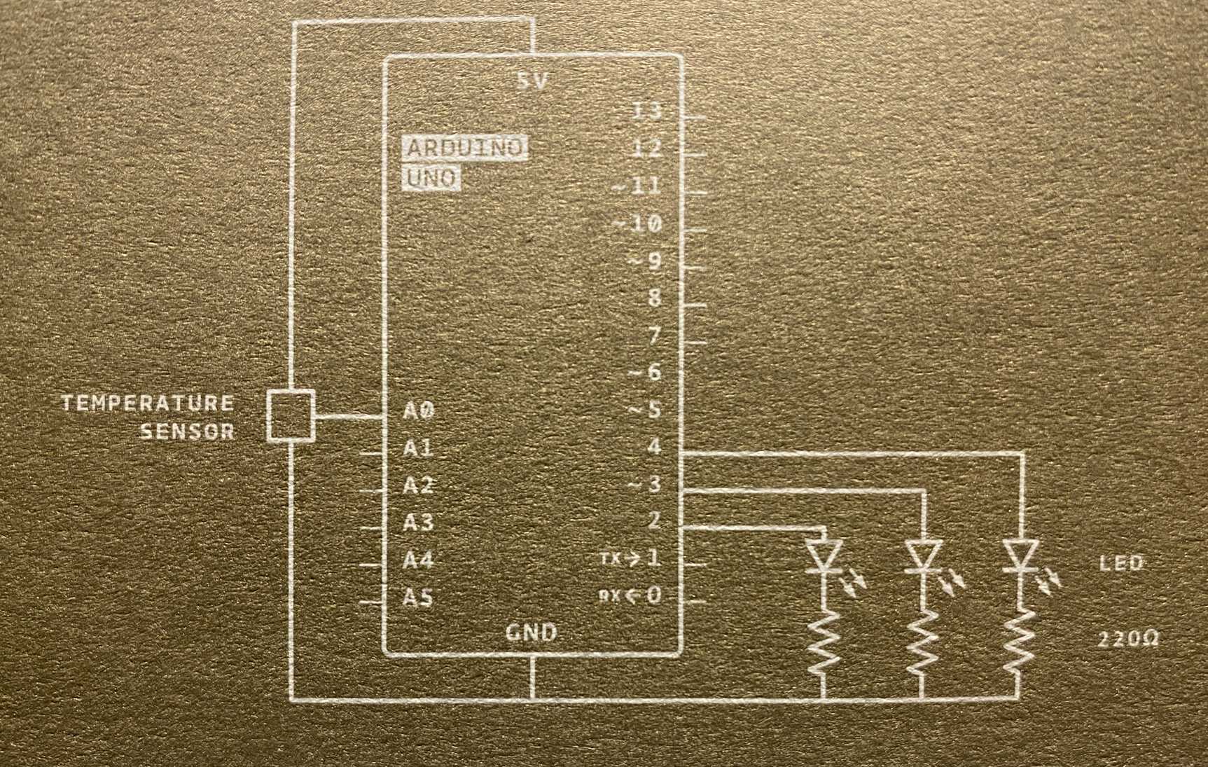
I used this schematic to connect everything.
The circuit setup was fairly easy. This is how it looks.
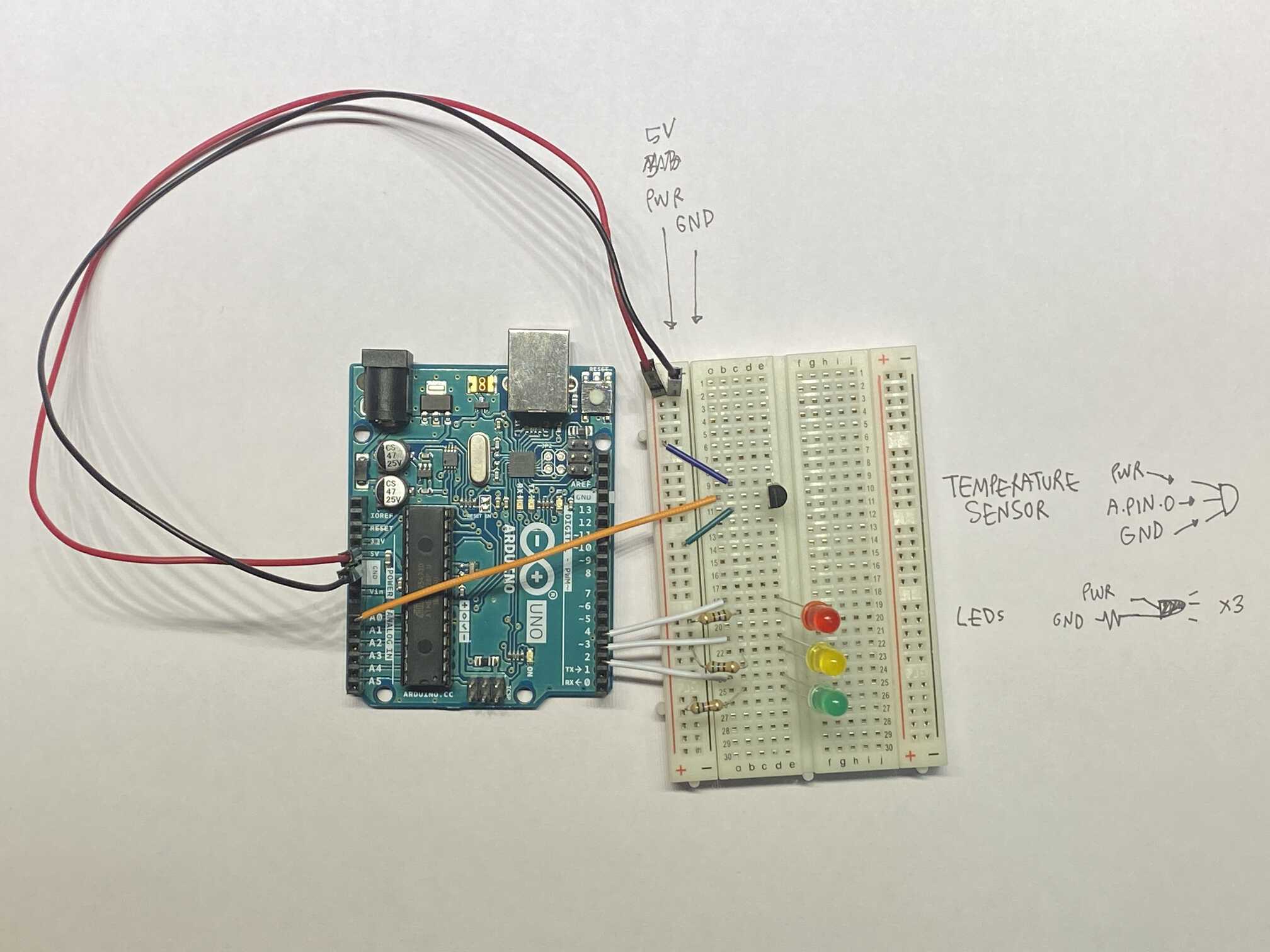 docs/images/inputs/setup.jpeg
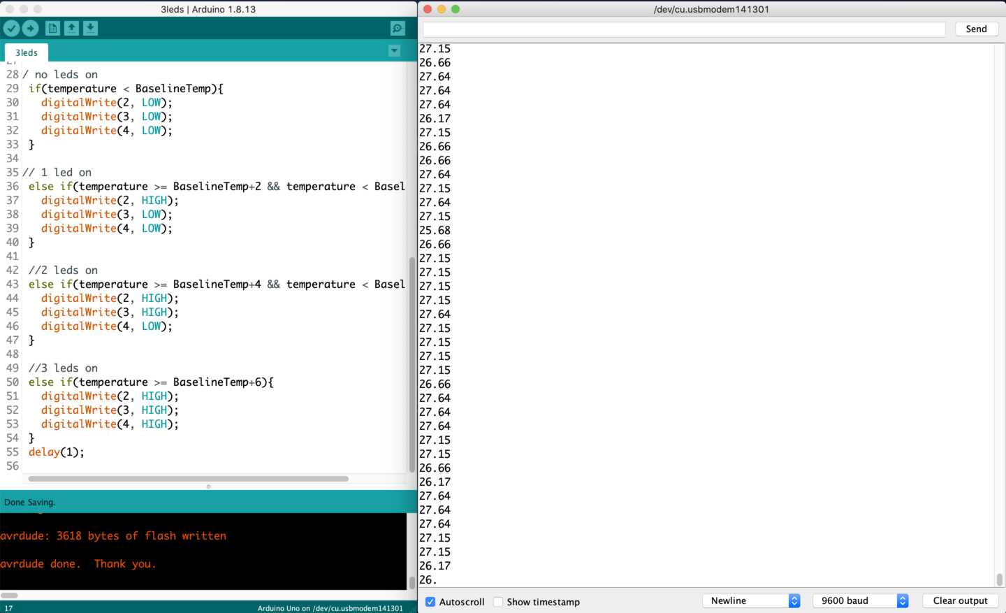
At first all lights were continuously on. I checked the serial monitor and saw that the temperature was around 26 degrees without touching. So I adjusted the baseline temperature to 25 in the sketch. After some trial and error, I adjusted the sketch so that on touching it lightly for about 5 seconds, the second led lit up and on holding it tight for some seconds the third led lit up. The serial monitor indicated temperature range from 26-32 degrees. So an increment of 2-4-6 degrees worked out perfectly.
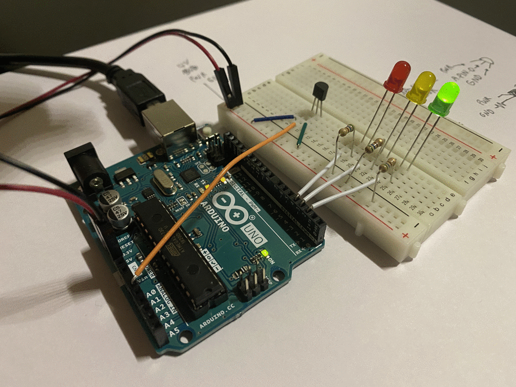
This is it in action.
####Code Sketch
####Tutorials Arduino Project 3
####Objective
- measure something: add a sensor to a microcontroller board that you have designed and read it
- probe an input device's analog levels and digital signals
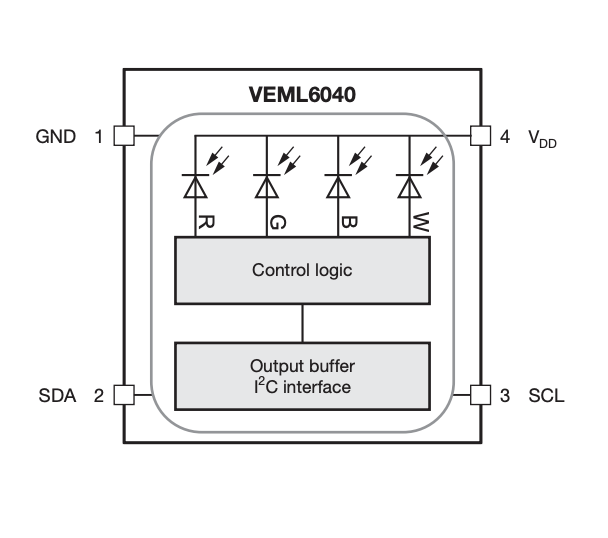
Measuring light color using a RGB colour sensor
#####Designing the board
Downloaded the footprint from Here
Installed the symbol and footprint on KiCAD using this guide


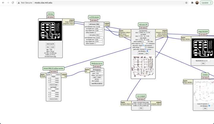

####Design Files


Schematic pdf
Schematic file
traces
Kicad pcbnew
References
https://en.wikipedia.org/wiki/List_of_sensors https://hackmd.io/RzTkiKoXTbqeQOn4Nz_zAw?view#INPUTS