# 3. Computer controlled cutting ## **Instruction** characterize your lasercutter's focus, power, speed, rate, kerf, joint clearance and types ## **Lesercutter we used** The following is information of the Lasercutter used at Fablab Kannai.  Universal VLS 2.3 - Work area is 406x305x102mm(16"x12"x4") - 30W CO2 ## **focus** 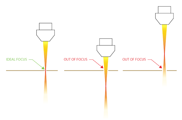 - Lens: 2.0 inch (2.54 x 2 mm) - Z Axis resolution 0.1mm - Defocus +5.0, +4.5, +4.0, +3.5, +3.0, +2.5, +2.0 +1.5, +1.0, +0.5, 0, -0.5, -1.0, -1.5 - material we used : card board 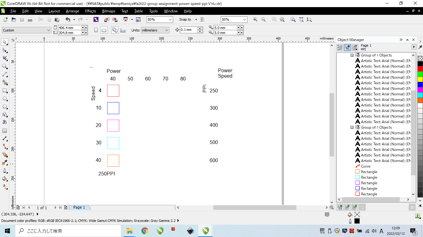 Set Z=0.6 as starting point(zero) and change z parameter by 5mm Unexpectedly, there is not a significant difference from the front viewpoint 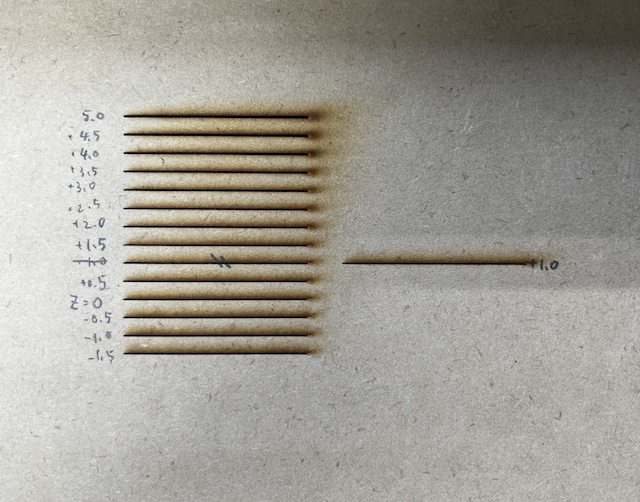 However, looking at the back we find the board is not cut enough above 3.5mm 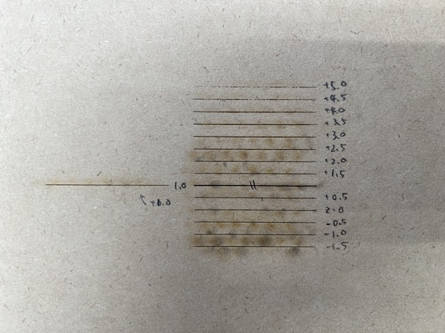 ## **Power, Speed, Rate** The data we used for power, speed, rate test - Power is laser output strength - Speed is speed of advancing laser - rate is PPI = pulses per inch  Only the column of power=40 is displayed and Command +P  Launch UCP software and select Medium Density Fiberboard at material database 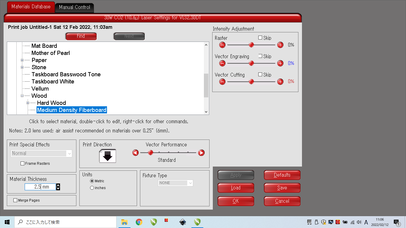 Cut the cardboard in each setting 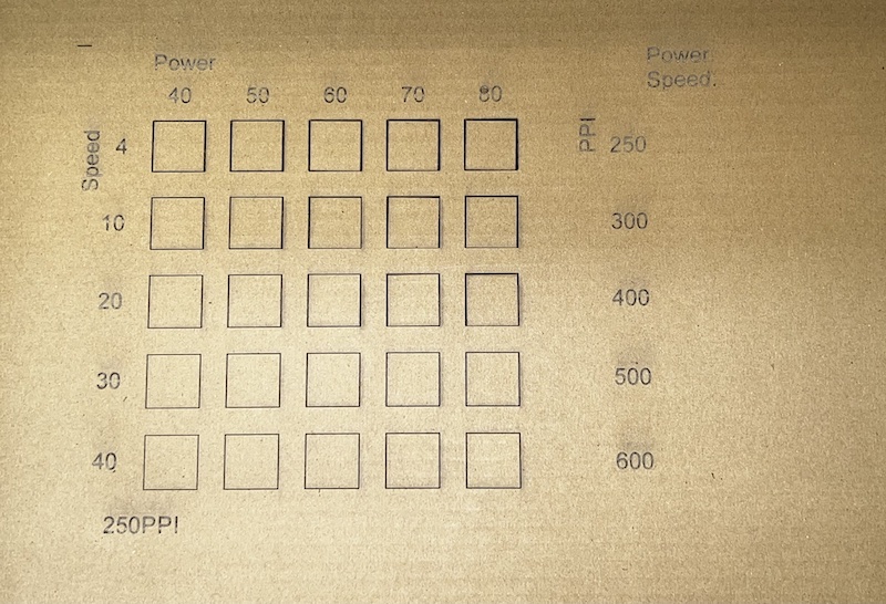 We found that the best setting for this cardboard is here **Power=70, Speed=20, PPI=250** 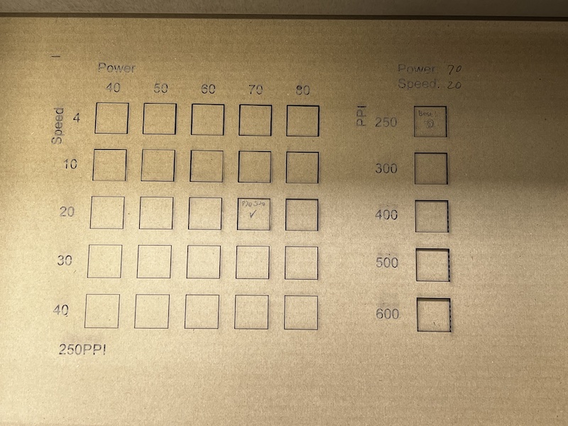 ## **kerf** In order to measure kerf, we use the data below. - 10 sticks (11 cuts) - 1/2 + 9 + 1/2 = 10 Kerf 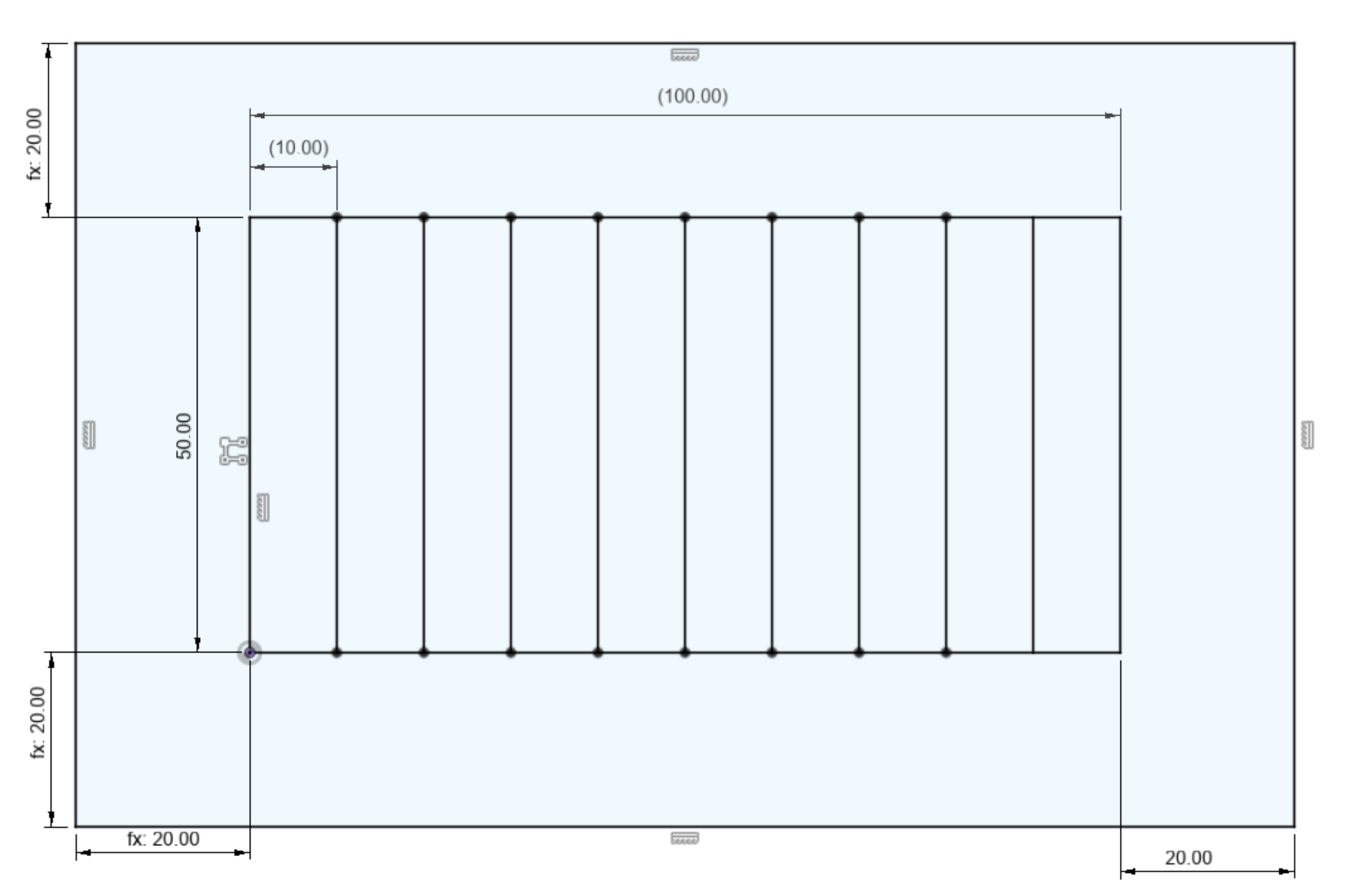 Cut the cardboard in the setting below **Power=70, Speed=20, PPI=250** 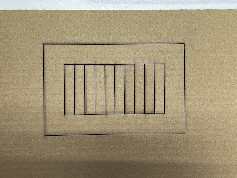 but the part of cardboard was not cut completely 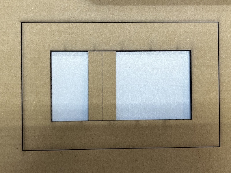 So we try again to cut it under a little stronger setting : **Power=70, Speed=10, PPI=250** This time I was able to cut it off completely. lay them side by side and measure the total lengry by digital caliper 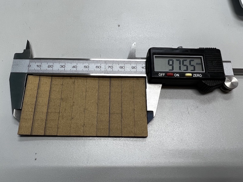 10 Kerf = 100 - 97.55 = 2.45 mm **kerf = 0.245 mm** ## **Joint Clearance for press-fit** Measure thickness of the cardboard 5 times and calculate the average for them 2.9 2.83 2.85 2.88 2.79 ave. **thickness = 2.85** We use the data for joint clearance test 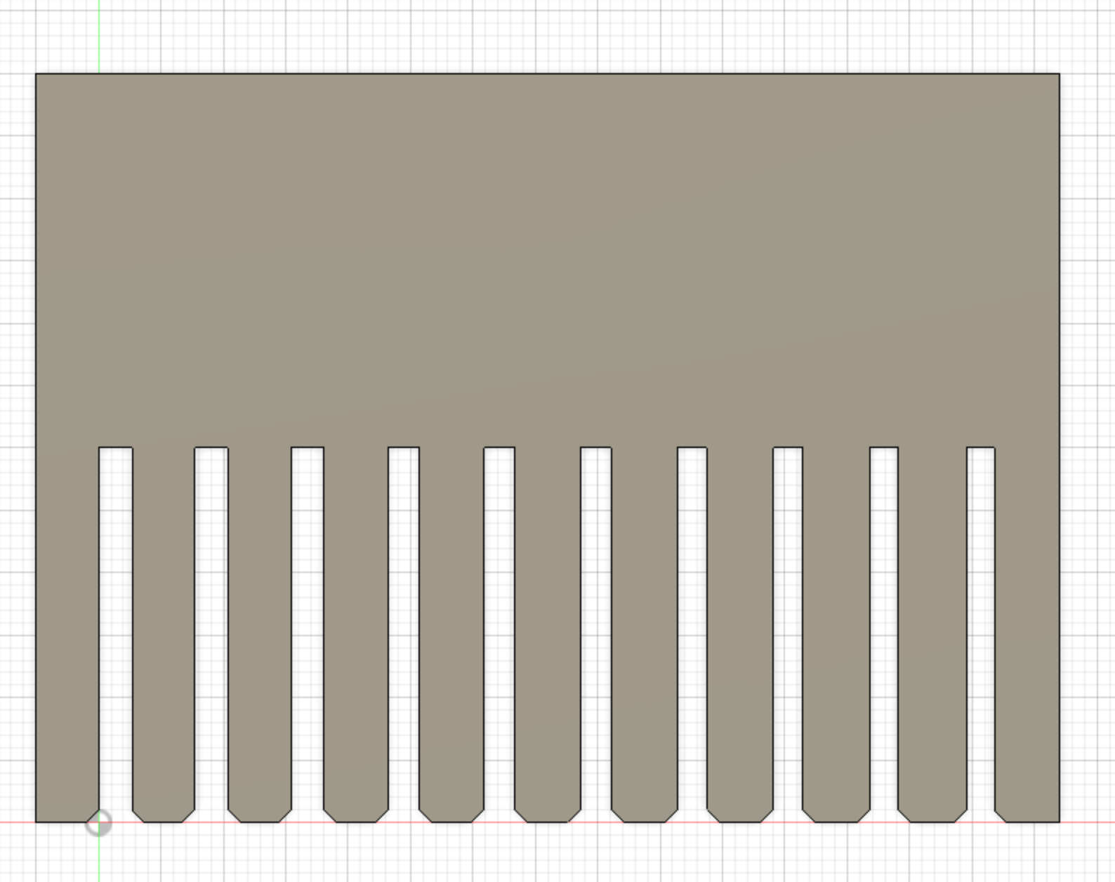 Set the result of experiment as parameter of thickness and kerf 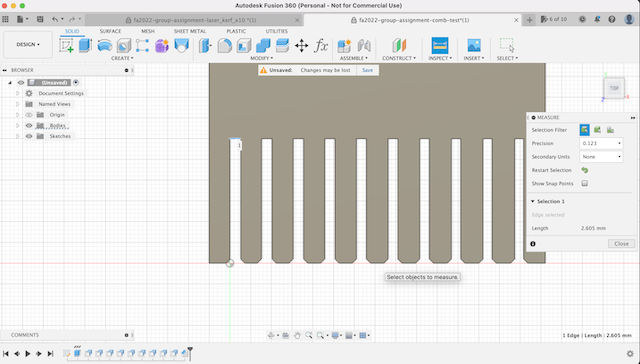 Cut the comb 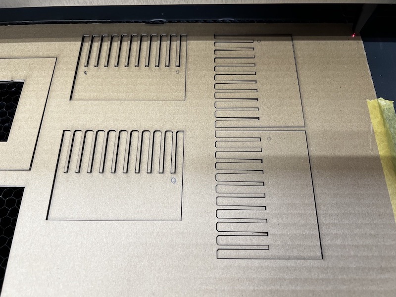 and we test which slit is the best fit 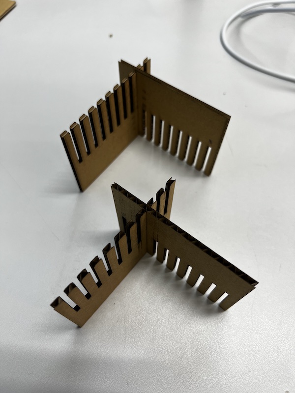 As a result, we get the final answer of the joint clearance as 0.1. So I found value of the best slit width below Thickness 2.85 -Kerf 0.245 -Joint Clearance 0.1 =2.505 ## **What we learn** to [Yukiya's individual site](https://fabacademy.org/2022/labs/kannai/students/yukiya-yamane/assignments/week04/) ## **Files we used** - [Power, Speed, Rate test](https://fabacademy.org/2022/labs/kannai/Instruction/images/week02/fa2021-group-assignment-power-speed-ppi.svg) - [Kerf test](https://fabacademy.org/2022/labs/kannai/Instruction/images/week02/fa2022-group-assignment-laser_kerf_x10%20.f3d) - [joint clearance test](https://fabacademy.org/2022/labs/kannai/Instruction/images/week02/fa2022-group-assignment-comb-test.f3d)