#### [notes](http://academy.cba.mit.edu/classes/networking_communications/index.html) + [video](https://vimeo.com/415632350) ### THIS WEEK'S ASSIGNMENTS 1. Group assignment: Send a message between two projects 2. Individual assignment: design, build, and connect wired or wireless node(s) with network or bus addresses This week's class had a lot of new information, so it was quite difficult for me to follow everything. ### THE BASICS Why Network? 1. Location 2. Parallelism 3. Modularity 4. Interference To understand basics of communication protocols, this [basics of protocols series on circuitsbasics.com](https://www.circuitbasics.com/basics-of-the-spi-communication-protocol) was very useful. For effective communication between electronic devices, they need to use the same language. This language is called communication protocol. Some basic protocols are *SPI, I2C and UART.* These are generally slower than protocols like *USB, ethernet, bluetooth and wifi*, but are ideal for communication between microcontrollers and sensors where the large amounts of high-speed data does not need to be transferred. Since I do not have access to a lab or a lot of inventory right now, I chose to understand wired communication protocols - SPI & I2C, with Arduino Unos that I do have access to. When I'm in the lab, or get more access to parts, I want to learn about the other wireless protocols too. #### Serial vs Parallel Communication While communicating, bits are transferred from one device to another by quick changes in voltage. In a 5V system, O corresponds to 0V and 1 corresponds to 5V voltage. In parallel communication, multiple bits are transferred at the same time through different wires. Whereas in series, the bits are transferred one after the other through the same wire. The following diagram shows the difference between the two. 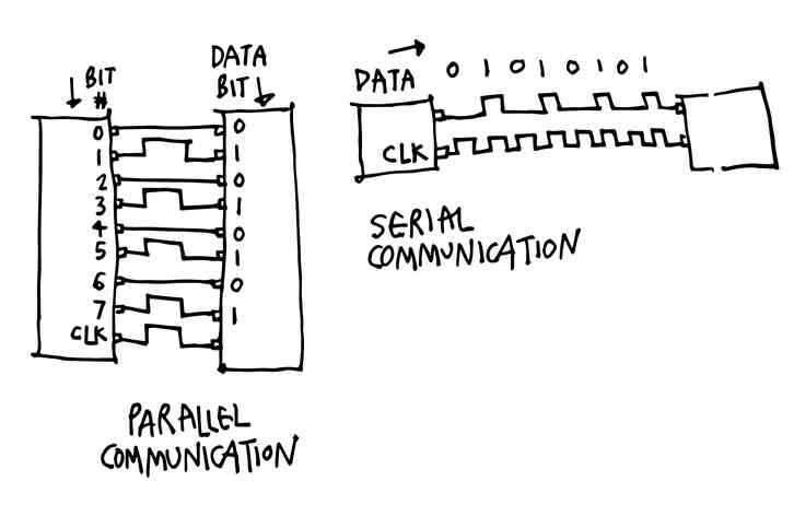 ### [SPI protocol](https://www.circuitbasics.com/basics-of-the-spi-communication-protocol) Serial-Peripheral Interface SPI is a common communication protocol used by many devices like SD card modules, RFID card reader modules. Unlike the other protocols (I2C and UART), SPI does not transfer data in packets. This means that any number of bits can be sent or received in a continuous stream without interruption in transmission. Devices communicating via SPI are in a master-slave(secondary) relationship. The master is the controlling device (usually a microcontroller), while the slave (usually a sensor, display, or memory chip) takes instruction from the master. This communication needs 4 lines: **MOSI (Master Output/Slave Input)** – Line for the master to send data to the secondary. **MISO (Master Input/Slave Output)** – Line for the secondary to send data to the master. **SCLK (Clock)** – Line for the clock signal. **SS/CS (Slave Select/Chip Select)** – Line for the master to select which secondary to send data to. 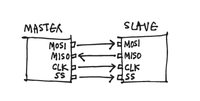 *Basic properties:* * 4 wires used * 10 Mbps maximum speed * Synchronous (devices share clock) & serial communication * 1 master can talk to (theoretically) unlimited number of secondaries How it works: **The clock** signal synchronizes the output of data bits from the master to the sampling of bits by the slave. One bit of data is transferred in each clock cycle, so the speed of data transfer is determined by the frequency of the clock signal. SPI communication is always initiated by the master since the master configures and generates the clock signal. The clock signal in SPI can be modified using the properties of clock polarity and clock phase. The master can choose which secondary it wants to talk to by setting the **Slave Select/Chip Select** line to a low voltage level. In an idle non-transmitting state, the SS line is at a high voltage level. Multiple CS/SS pins may be available on the master, which allows for multiple slaves to be wired in parallel. If only one CS/SS pin is present, multiple slaves can be wired to the master. 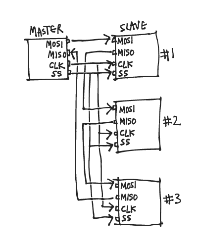 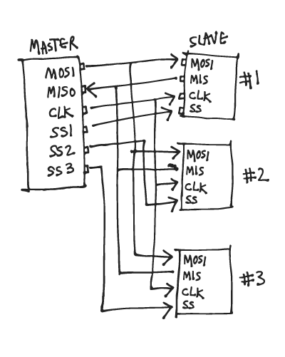 The master sends data to the secondary bit by bit, in serial through the **MOSI** line. The secondary receives the data sent from the master at the **MOSI** pin. 1. The master outputs the clock signal first. 2. The master switches the SS/CS pin to a low voltage state, which activates the secondary. 3. The master sends the data one bit at a time along the MOSI line. The secondary reads the bits as they are received. 4. If a response is needed, the secondary returns data one bit at a time to the master along the MISO line. The master reads the bits as they are received. ### [UART protocol](https://www.circuitbasics.com/basics-uart-communication/) Universal Asynchronous Receiver/Transmitter UARTs are good to connect GPS modules, Bluetooth modules, and RFID card reader modules to Raspberry Pi, Arduino, or other microcontrollers. Unlike SPI and I2C, UART is not exactly a communication protocol, but a physical circuit in a microcontroller, or a stand-alone IC. A UART’s purpose is to transmit and receive serial data.  It only uses two wires to transmit data between devices asynchronously, meaning there is no clock signal to synchronize the output of bits from the transmitting UART to the sampling of bits by the receiving UART. Instead, the transmitting UART adds start and stop bits to the data packet being transferred. These bits define the beginning and end of the data packet so the receiving UART knows when to start reading the bits. This reading is done at a specific frequency known as the baud rate. Baud rate is a measure of the speed of data transfer, expressed in bits per second (bps). Both UARTs must operate at about the same baud rate.  *Basic properties:* * 4 wires used * 115200 maximum baud, avg is 9600 baud * Asynchronous (without clock) & serial communication * 1 master and 1 secondary  **Start bit** When the receiving UART detects the high to low voltage transition, it begins reading the bits in the data frame at the frequency of the baud rate. The **data frame** contains the actual data being transferred. **Parity** describes the evenness or oddness of a number. If data has changed during transmission by electromagnetic radiation, mismatched baud rates, or long distance data transfers. 0 for even and 1 for odd, when the parity bit matches the data, the UART knows that the transmission was free of errors. To signal the end of the data packet, the sending UART drives the data transmission line from a low voltage to a high voltage for at least two bit durations in the **stop bit**. ### [I2C protocol](https://www.circuitbasics.com/basics-of-the-i2c-communication-protocol/) I2C stands for-Inter Integrated Circuit. I2C communication allows for a single or multiple masters (unlimited) to talk to a single or multiple secondaries (max. 1008). It uses two wires to transmit data between devices. Since it follows series communication, it transfers bits one by one through the same wire. 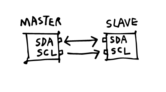 **SDA (Serial Data)** - to send as well as receive data between the master/s and secondary/s **SCL (Serial Clock)** - sends the clock signal The clock signal is controlled by the master, and the data is *synchronized* to the bit sampling. Data is sent in messages. Here is a diagram of the structure of a message. 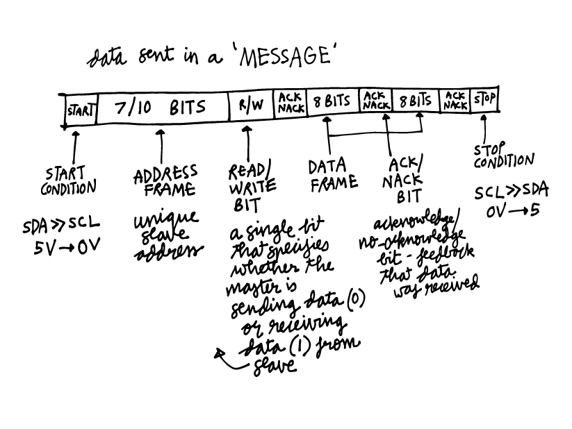 A pull-up resistor needs to be connected from the Master's SDA and SCL each to VCC, if there are more than one secondaries or more than one masters. Since I have access to some Arduino Unos, I tried [this guide on Instructables](https://www.instructables.com/Arduino-I2C-and-Multiple-Slaves/) to explore the communication between various numbers of masters and secondaries. Arduino Uno has I2C pins: **A5** is SCL **A4** is SDA as shown in this [Arduino pinout diagram by pighixxx](https://commons.wikimedia.org/wiki/File:Pinout_of_ARDUINO_Board_and_ATMega328PU.svg).  #### **I2C with one master and one secondary** [Reference](https://www.instructables.com/Arduino-and-I2C/) ##### Hardware required: * 2x Arduino Unos * Hook-up wires ##### Circuit: Using the pinout, I first made the circuit with these steps: 1. Connected GND of both Arduinos. 2. Connected analog pin A5 to A5 (SCL) and analog pin A4 to A4 (SDA). 3. Powered up both Arduinos by connecting them to my computer, and setting the boards ands ports for both. ##### Code [Master Code](./images/nc/1M1S/i2c_with_1_master_and_1_slave1.ino) [Secondary Code](./images/nc/1M1S/i2c_with_1_master_and_1_slave2.ino) On opening the serial monitor, you can see messages sent from one to the other:  ##### I2C with one master, multiple secondaries. 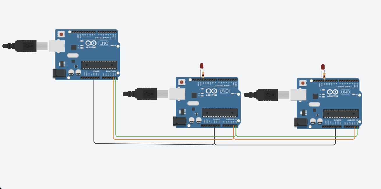 ##### I2C with multiple masters and secondaries. Want to learn about MQTT protocol. ### STUDENT CHECKLIST 1. Linked to group assignment page 2. Documented your projects 3. Documented what you have learnt fromimplementing networking and/or communication protocols 4. Explained the programming process/es you used 5. Outlined problems and how you fixed them 6. Included design files (or linked to) ### DESIGN FILES #### Bridge * [schematic](./images/nc/Networking-bridge.pdf)   #### Node * [schematic](./images/nc/Node.pdf)