#### [notes](http://academy.cba.mit.edu/classes/interface_application_programming/index.html) + [video](https://vimeo.com/412495586)
This week is about writing an application that can be interfaced by a user with an external input &/or output device.
Software programming is completely new for me. So I'm going to try briefly whatever I can.
Processing
---
I start with processing as suggested by Steven.
A good way to learn about the what and why of 'Processing' is this essay ['A Modern Prometheus'](https://medium.com/processing-foundation/a-modern-prometheus-59aed94abe85) by the initiators of the project.
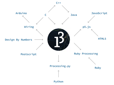
Processing is basically a program that connects graphic design to computer science. It has a set of elements for creating visual design with code. The processing website has a good set of [video tutorials that covers the basics](https://processing.org/tutorials/).
Here is a screenshot of a sketch I wrote while learning the basics of the code structure, the void setup and draw, the-coordinate system, and use simple visual elements - shape, colour in greyscale and rgb, interact with the mouse, conditional statements...
The processing PDE (processing development environment) looks very similar to the Arduino IDE (integrated Development Environment). I learnt that the Arduino Env was inspired by the Processing Env, and in the process learnt how python and other coding systems are all related and are developed from each other.
After playing around with some examples from the P3 library, I really like the program, there are some features like tweak (that visually helps tweak variable values), the error message (that clearly states the error in the code, instead of giving generic error 403292348 that you don't really understand). I look forward to using a lot of [libraries](https://processing.org/reference/libraries/) and the the debugger () that really makes it easy and fun to use.
I found that keeping the [Programming reference](file:///Applications/Processing.app/Contents/Java/modes/java/reference/index.html) open is quite useful while making a sketch from scratch.
Software Switch + hardware LED using Processing & Arduino IDE
---
For this week's assignment I do a simple virtual switch. A button made in processing will control a hardware LED connected to Arduino. With the help of [this guide](https://tutorial.cytron.io/2019/07/26/simple-gui-to-control-led-on-arduino-with-processing/).
The code for Arduino is [here](./images/app/LED_GUI_A.zip). Upload it to an Arduino Uno which has an external LED & resistor connected to Pin 3.
To check it you can open the serial monitor, and on typing in 't' you can switch on and switch off the LED like so:
<iframe
src="http://academany.fabcloud.io/fabacademy/2020/labs/barcelona/students/mitalee-parikh/app-1.mp4">
</iframe>
The code for Processing is [here](./images/app/LED_GUI_P.zip).
You need to mention the port of the Arduino in the processing sketch to interface them together. You can find the port name by typing in this in the terminal:
```
ls /dev/tty.usb*
```
This lists the serial ports connected on Mac OS system. Run the P3 program, and a virtual button will pop up.
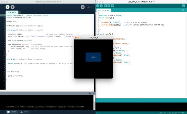
You can control the external LED through the virtual button like so:
<iframe
src="http://academany.fabcloud.io/fabacademy/2020/labs/barcelona/students/mitalee-parikh/app-2.mp4">
</iframe>
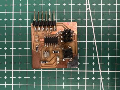
Next, I use the hello board I made in electronic design week to interface with a software switch.
This board has:
LED on pin 8 (PB2)
Button on pin 7 (PA7)
Tx on pin 0
Rx on pin 1
First step is to program the hello board using FabISP.
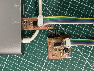
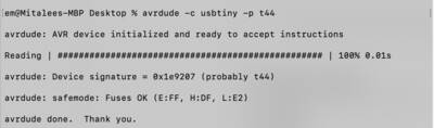
In terminal check if the board is detected using avrdude.
The code:
```
#include <SoftwareSerial.h>
#define rx 1
#define tx 0
#define led 8 // declare variables
SoftwareSerial mySerial(rx,tx);
char val; // data received from serial port
void setup() {
// put your setup code here, to run once:
pinMode(led, OUTPUT); // configure led pin as output
mySerial.begin(9600); // set serial port to 9600 bps
}
void loop() {
if (mySerial.available()){
// If data is available to read,
val = mySerial.read(); // read it and store it in val
if (val == '1'){ // If 1 was received
digitalWrite(led, HIGH); // turn the LED on
} else if (val == '0'){
digitalWrite(led, LOW); // otherwise turn it off
}
delay(10); // Wait 10 milliseconds for next reading
}
}
```
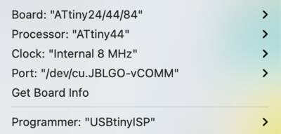
After compiling and uploading using programmer with these settings, disconnect the FabISP.
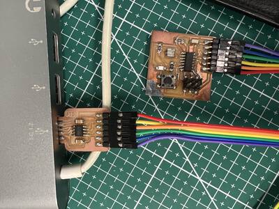
Next, plug in the hellp board with ftdi wire, I will use a diy ftdi board to do this.
Change the port to serial port in the 'Tools' drop down and open the serial monitor.
On input 1 the LED on the board should blink and on input 0, LED should switch off.
<iframe
src="http://academany.fabcloud.io/fabacademy/2020/labs/barcelona/students/mitalee-parikh/app-1.mp4">
</iframe>
Now that the serial connection is working, open Processing.
The code:
```
import processing.serial.*;
Serial myPort; // Create object from Serial class
int ledState = 0; // start with led OFF
int r = 0; // start with black (led OFF)
int g = 0;
int b = 0;
void setup()
{
size(200,200); //make our canvas 200 x 200 pixels big
myPort = new Serial(this, "/dev/cu.usbserial-14310", 9600);
}
void draw() {
background(255); // set background to white
fill(r,g,b);
rect(25, 25, 150, 150);
}
void mouseReleased(){
if (ledState == 0){
ledState = 1; // toggle led state
r = 0; // set fill color to black
g = 0;
b = 0;
myPort.write('1'); //send a 1
println("1");
} else { //otherwise
ledState = 0;
r = 255; // set fill color to golden yellow
g = 184;
b = 28;
myPort.write('0'); //send a 0
println("0");
}
}
```
Check the serial port name in the code. On running, the GUI serial will show the rectangular virtual switch. On clicking it, the LED of the hello board should switch on and off.
<iframe
src="http://academany.fabcloud.io/fabacademy/2020/labs/barcelona/students/mitalee-parikh/app-2.mp4">
</iframe>
Hardware Switch + Software LED using Processing & Arduino IDE
---
I will use the same hello board which has a push button to trigger colour on a "virtual led" on the serial screen.
The hello board has the same pins stated above:
LED on pin 8 (PB2)
Button on pin 7 (PA7)
Tx on pin 0
Rx on pin 1
This time the code for Arduino:
```
#include <SoftwareSerial.h>
#define rx 1
#define tx 0
#define pb 7
// declare variables
SoftwareSerial mySerial(rx,tx);
int pbState = 0;
void setup() {
// put your setup code here, to run once:
pinMode(pb, INPUT_PULLUP); // configure pb pin as input
mySerial.begin(9600); // initialize serial port
}
void loop() {
// put your main code here, to run repeatedly:
if (digitalRead(pb) == LOW){ // pb pressed
delay(10); // switch debounce
while (digitalRead(pb) == LOW); // wait for pb release
if (pbState == 0){ // check current state
pbState = 1; // update to new state
}
else if (pbState == 1){ // check current state
pbState = 0; // update pb state
}
mySerial.print(pbState); // output current pb state
}
}
```
After flashing this, check the serial communication again. Plug out FabISP, plug in ftdi, change to serial port in tools dropdown and open serial monitor. This time, on pressing the pushbutton on the hello board, the serial monitor should return a 0 or a 1.
<iframe
src="http://academany.fabcloud.io/fabacademy/2020/labs/barcelona/students/mitalee-parikh/app-3.mp4">
</iframe>
After checking this, open processing again and the code:
```
import processing.serial.*;
Serial port; // Create object from Serial class
int val = '0'; // Data received from the serial port, start black
void setup() {
size(200, 200);
frameRate(10);
// Open the port that the board is connected to and use the same speed (9600 bps)
port = new Serial(this, "/dev/cu.usbserial-14310", 9600);
}
void draw() {
if (port.available() > 0) { // If data is available,
val = port.read(); // read it and store it in val
}
background(255); // Set background to white
if (val == '0') { // If the serial value is 0,
fill(0); // set fill to black
} else if (val == '1'){ // If the serial value is not 0,
fill(255,184,28); // set fill to golden yellow
}
rect(50, 50, 100, 100);
}
```
Run this after changing to the correct port name and then the pushbutton should be able to change the screen colour.
To give the effect of led I made it black and yellow.
<iframe
src="http://academany.fabcloud.io/fabacademy/2020/labs/barcelona/students/mitalee-parikh/app-4.mp4">
</iframe>
This way, hardware and virtual input outputs can be used together.
Code Files
---
**Virtual switch + hardware LED**
[Arduino Code](./images/app/t44_ledCtrl.zip)
[Processing Code](./images/app/t44_ledCtrl_pde.zip)
**Hardware pushbutton + virtual LED**
[Arduino Code](./images/app/t44_pbToggle.zip)
[Processing Code](./images/app/t44_pbToggle_pde.zip)
References
---
[Processing story](https://medium.com/processing-foundation/a-modern-prometheus-59aed94abe85)
[Processing tutorials](https://processing.org/tutorials/)
[connecting Arduino & Processing with this sparkfun guide](https://learn.sparkfun.com/tutorials/connecting-arduino-to-processing/all#introduction)
[Arduino + Processing](https://processing.org/tutorials/electronics)
[sparkfun tutorial](https://learn.sparkfun.com/tutorials/connecting-arduino-to-processing/all)
[Radar Project](https://howtomechatronics.com/projects/arduino-radar-project/)
[with BT module](https://randomnerdtutorials.com/getting-started-with-mit-app-inventor-2-and-arduino/)
[MIT app inventor + arduino](https://howtomechatronics.com/tutorials/arduino/how-to-build-custom-android-app-for-your-arduino-project-using-mit-app-inventor/)
[MIT app inventor](https://appinventor.mit.edu/)
[ai2](http://ai2.appinventor.mit.edu/)
[with python + tk](http://arduinolearning.com/code/led-control-with-arduino-and-python-tkinter.php)
[this doc](http://archive.fabacademy.org/fabacademy2017/fablabsingapore/students/216/exercise16.html)
[and this](http://fab.academany.org/2020/labs/singapore/students/noel-kristian/exercise12.html)
[and this](https://eatpoopandgrowstrong.github.io/FDFAB/hub/interfacingandapplicationsprogramming.html)
[Open Processing](https://openprocessing.org/)
[D3js](https://d3js.org/)
[P5js](https://p5js.org/)