-
Mitalee Parikh authoredMitalee Parikh authored

- notes + video
- THIS WEEK'S ASSIGNMENTS
- THE BASICS
- Serial vs Parallel Communication
- SPI protocol
- UART protocol
- I2C protocol
- I2C with one master and one secondary
- Hardware required:
- Circuit:
- Code
-
-
- I2C with one master, multiple secondaries.
- I2C with multiple masters and secondaries.
- STUDENT CHECKLIST
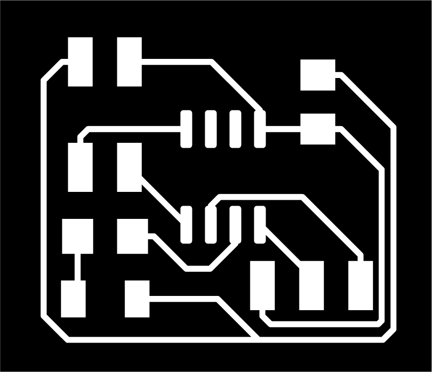
- DESIGN FILES
- Bridge
- Node
notes + video
THIS WEEK'S ASSIGNMENTS
- Group assignment: Send a message between two projects
- Individual assignment: design, build, and connect wired or wireless node(s) with network or bus addresses This week's class had a lot of new information, so it was quite difficult for me to follow everything.
THE BASICS
To understand basics of communication protocols, this basics of protocols series on circuitsbasics.com was very useful. For effective communication between electronic devices, they need to use the same language. This language is called communication protocol. Some basic protocols are SPI, I2C and UART. These are generally slower than protocols like USB, ethernet, bluetooth and wifi, but are ideal for communication between microcontrollers and sensors where the large amounts of high-speed data does not need to be transferred.
Since I do not have access to a lab or a lot of inventory right now, I chose to understand wired communication protocols - SPI & I2C, with Arduino Unos that I do have access to. When I'm in the lab, or get more access to parts, I want to learn about the other wireless protocols too.
Serial vs Parallel Communication
While communicating, bits are transferred from one device to another by quick changes in voltage. In a 5V system, O corresponds to 0V and 1 corresponds to 5V voltage. In parallel communication, multiple bits are transferred at the same time through different wires. Whereas in series, the bits are transferred one after the other through the same wire. The following diagram shows the difference between the two.

SPI protocol
Serial-Peripheral Interface
UART protocol
Universal Asynchronous Receiver/Transmitter
I2C protocol
I2C stands for-Inter Integrated Circuit.
I2C communication allows for a single or multiple masters (unlimited) to talk to a single or multiple secondaries (max. 1008). It uses two wires to transmit data between devices. Since it follows series communication, it transfers bits one by one through the same wire.
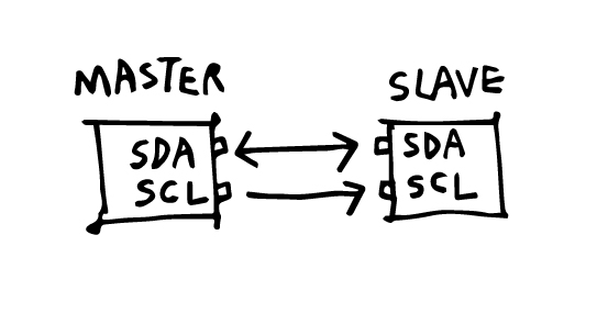
SDA (Serial Data) - to send as well as receive data between the master/s and secondary/s
SCL (Serial Clock) - sends the clock signal
The clock signal is controlled by the master, and the data is synchronized to the bit sampling.
Data is sent in messages. Here is a diagram of the structure of a message.

A pull-up resistor needs to be connected from the Master's SDA and SCL each to VCC, if there are more than one secondaries or more than one masters.
Since I have access to some Arduino Unos, I tried this guide on Instructables to explore the communication between various numbers of masters and secondaries.
Arduino Uno has I2C pins:
A5 is SCL
A4 is SDA
as shown in this Arduino pinout diagram by pighixxx.

I2C with one master and one secondary
Hardware required:
- 2x Arduino Arduinos
- Hook-up wires
Circuit:
Using the pinout, I first made the circuit with these steps:
- Connected GND of both Arduinos.
- Connected analog pin A5 to A5 (SCL) and analog pin A4 to A4 (SDA).
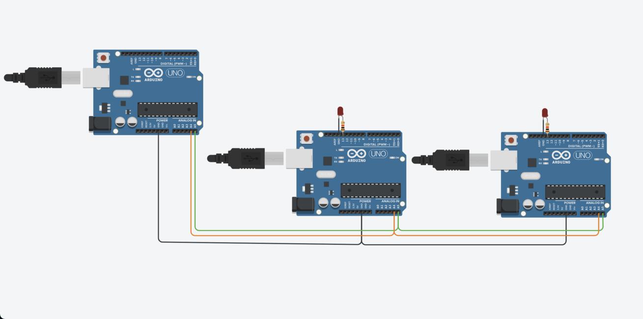
- Powered up both Arduinos by connecting them to my computer, and setting the boards ands ports for both.
Code


I2C with one master, multiple secondaries.
I2C with multiple masters and secondaries.
Want to learn about MQTT protocol.
STUDENT CHECKLIST
- Linked to group assignment page
- Documented your projects
- Documented what you have learnt fromimplementing networking and/or communication protocols
- Explained the programming process/es you used
- Outlined problems and how you fixed them
- Included design files (or linked to)